TM 10-4930-220-13&P
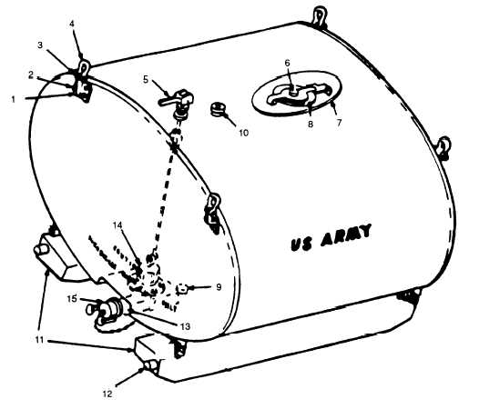
1. Bracket
5. Control lever
9. Drain plug
13. Emergency dump valve
2. Bolt
6. Vent assembly
10. Pump port
14. Inlet strainer valve
3. Nut
7. Manhole cover
11. Skids
15. Dust cap
4. Lifting eye
8. Filler plug
12. Interlock
Figure 1–2. Tank unit assembly (Advanced Model TRL 1000).
a.
Skids. Used to stabilize the Tank Unit Assembly and provide a place for it to be mounted (16 Figure 1-1
and 11, Figure 1–2)
b. Emergency Dump Valve. Used for dispensing liquid. Located on the bottom front of the Tank Unit be-
tween the skids (13, Figure 1–1 and Figure 1 –2)
c.
Tank. Used for storage and transporting of liquid petroleum products (Figure 1–1 and Figure 1 –2)
1-3