SERVICE MANUAL
RESERVOIR AUTOMATIC DRAIN VALVE
DESCRIPTION
The DV-2 Reservoir Automatic Drain Valve ejects
moisture and contaminants from the reservoir in which it
is connected. It operates automatically and requires no
manual assistance or control lines from other sources.
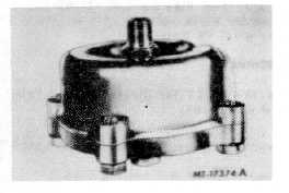
The reservoir automatic drain valve has a die cast
aluminum body and cover and is normally mounted
either in the bottom of the reservoir using the top port of
the drain valve or in the end of an end drain reservoir
using the side port of the valve.
For vehicles operating in subfreezing temperatures,
the valve is also available with a heater and thermostat
cast into the cover.
Fig. 7 Reservoir Automatic Drain Valve
OPERATION
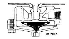
With no air pressure in air system, the inlet and exhaust
valves are closed (Fig. 8).
Fig. 8
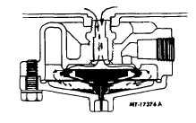
When charging the air system, a slight pressure opens
the inlet valve which permits air and contaminants to
collect in sump (Fig. 9).
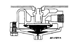
The inlet valve remains open while pressure ascends in
the system until maximum governor cut-out pressure is
reached. The spring action of valve guide in sump cavity
closes the inlet. The inlet valve and exhaust valve are
now closed (Fig. 10).CTS-4079
Fig. 9
Fig. 10
When reservoir pressure drops slightly (approximately
13.8 kPa - 2 psi), air pressure in the sump cavity opens
exhaust valve allowing moisture and contaminants to be
ejected from sump cavity until pressure in sump cavity
drops sufficiently to close the exhaust valve. The length
of time the exhaust valve remains open and the amount
of moisture and contaminants ejected depends upon the
sump pressure and reservoir pressure drop that occurs
each time air is used from the system.
Fig. 11
Manual draining can be accomplished by inserting a tool
in the exhaust port so that the wire in the port may be
moved up and held until draining is completed.
CTS -4079-CHAPTER II -
PRINTED IN UNITED STATES OF AMERICA
Page 7