SERVICE MANUAL
INVERSION VALVE
DESCRIPTION
The inversion valve is a Bendix, TR-3 valve, which is a
pilot operated, non-graduated two way valve. The valve
will be found in the cruise control system where it
functions as an on-off air control valve.
When operating the vehicle with the cruise control in
cruise mode, air will pass through the valve. When the
service brakes are applied through the foot (brake) valve
or the hand control valve the inversion valve will exhaust
air in the cruise system, thus releasing the cruise control
system.
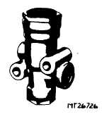
Fig. 8 Emergency Relay Valve
The TR-3 type valve has a separate control port and
supply port; and depending upon the piping of the
vehicle, the control port can either be piped to a separate
air supply or can be piped so that the control and air
supply air pressure are from a common air supply. In the
application of cruise control system the supply port will
be connected to the solenoid control assembly, the
control port will be connected to the tractor protection
valve and the delivery port will be connected to the air
cylinder assembly. For complete operational description
of the cruise control system refer to CRUISE CONTROL
in ELECTRICAL GROUP.
OPERATION
Refer to Fig. 9 for numbers and letters in parenthesis.
With no air pressure at the control port (D) the piston
spring (11) forces the piston (9) against the inlet valve (7)
closing the exhaust passage in the hollow piston stem.
The inlet valve (7) is open allowing air passage from the
solenoid valve through the supply port (C) and out the
delivery port (B).
When the service brakes are applied through the brake
valve or hand control valve the air
CTS-4079 - CHAPTE
pressure will enter the control port (D) pushing piston (9)
away from its seat and at the same time forcing the
piston away from the inlet valve (7) which is held closed
by the valve return spring (4). At this time the delivery
line to the air cylinder is vented to atmosphere through
the hollow exhaust stem in the piston (9) and out the
exhaust port (A), releasing the cruise control. The inlet
valve is also closed off at this time sealing the supply
from the solenoid valve assembly.
Fig. 9 Crow Section of Emergency Relay Valve
A.
Exhaust Port
B.
Delivery Port
C.
Supply Port
D.
Control Port
1.
Diaphragm
2.
Exhaust Nut
3.
O-Ring
4.
Valve Spring
5.
Cap
6.
Valve Stop
7.
Valve
8.
Shim
9.
Piston
10.
Diaphragm Retainer
11.
Piston Spring
MAINTENANCE
Once each year or every 160,000 km (100,000 miles)
perform the LEAKAGE TEST If the valve failed the
leakage test it must be replaced.
CTS-4079-CHAPTER III
PRINTED IN UNITED STATES OF AMERICA
PAGE -8