SERVICE MANUAL
2.
Bleed air from main air reservoir.
3.
Locate outlet port on air dryer assembly which is
the air supply to main air reservoir. Then
disconnect the air supply line or hose.
4.
After hose is disconnected, the elbow and check
valve assembly can then be removed separately.
5.
Install new check valve assembly and seal.
6.
Reinstall elbow and connect hose.
7.
After air supply is restored, check connection for
air leaks.
CR BRAKEMASTER 62 & 68 MODELS
DISCRIPTION
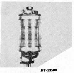
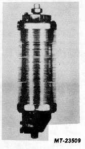
The CR Brakemaster units (Figs. 21 & 22) are
actually heat exchangers since the compressed air from
the air compressor is cooled.
When the compressed air leaves the air compressor,
it is about 1490 C (3000 F) and by the time it reaches the
Brakemaster unit, the temperature will drop to about 600
C (1400 F).
Fig. 21 CR Brakemaster Model 62
The hot compressed air enters the expansion
chamber where the sudden drop in pressure cools it off.
The heat is carried away through the external fins which
are an integral part of the one piece aluminum body.
As the air cools in the expansion chamber, both
water
and
oil
vapors
are
condensed
out.
This
condensation collects on the walls of the expansion
chamber and runs down into the collection area where it
Fig. 22 CR Brakemaster Model "8
is automatically discharged by a specially designed
unloader valve.
The heat exchanger has a permanent air filter
element which traps carbon particles that can harm other
components in the air system. Every time the unloader
operates (each time the compressor completes a cycle)
there is a back rush of air through the filter, so that any
carbon trapped in the filter element is flushed out and
ejected through the unloader valve.
In an air system where the compressor is in good
condition, the filter will require little or no maintenance. If
the filter should require servicing, it should only need a
bath in cleaning solvent. Replacement should be
unnecessary.
MAINTENANCE
Periodic or scheduled maintenance is not required.
However, for trouble free operation, the following items
should be checked.
1.
Steam clean cooling fins to remove accumu-
lated road grime.
2.
Check to be sure cooling fins have not been
painted.
3.
Check air lines to be sure they have not be-
come kinked, cracked, broken or chafed.
4.
Perform the Service Checks.
CTS-4079 - CHAPTER XIV - Page 12


