ENGINE DIAGNOSTIC TEST PROCEDURES
Section 6
-IMPORTANT-
IF
THESE
RESISTANCE
SPECIFICATIONS ARE NOT
MET,
REPLACE
THE
SOLENOID.
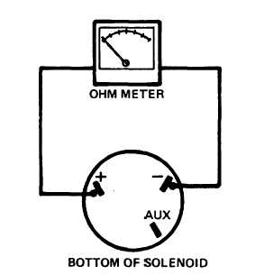
RESISTANCE CHECK
(NO POWER TO SOLENOID
IGNITION SWITCH OFF)
PLUNGER
POSITION
OHMS
OUT
0.2-0.3
IN
18-20
CG-9838
Figure 10. Solenoid Resistance Check
NOTE: " AUX" terminal is present only on early
model solenoids.
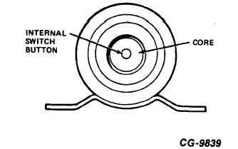
INTERNAL SWITCH DESCRIPTION
(Refer to Figure 11)
The solenoid contains a built-in switch that is activated
when plunger nears the bottom of its stroke. The switch
button extends from the bottom of the solenoid end cap
into the core.
The switch should completely return to the "out" position
when plunger is out. If switch does not rapidly return to
the "out" position, debris has fouled the switch and
solenoid must be replaced.
Figure 11. Solenoid Internal Switch Button
Located in Bottom of Solenoid Core
CGES-2404
Printed in United States of America
Page 20


