TM 5-3825-226-24
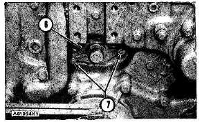
LOCATION OF COVER
6. Cover for the tachometer drive assembly. 7. Nuts.
NOTE
On Models 613BSS1 and 613BSNS1
cover
is
replaced
with
angular
tachometer drive assembly.
a.
Remove nuts (7) and the cover for the
tachometer drive assembly (6).
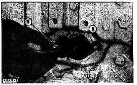
b.
Remove the tachometer drive shaft (9) and
washer (8) from the camshaft for the fuel
injection pumps.
NOTE
Tachometer
drive
shaft
(9)
and
washer (8) are removed as an
assembly.
LOCATION OF BOLT
8. Washer. 9. Tachometer drive shaft.
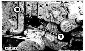
LOOSENING DRIVE GEAR
10. 5P2371 Puller. 11. Bolts.
c.
Put 5P2371 Puller (10) on-the camshaft for the
fuel injection pumps. Tighten bolts (11) until the
drive gear on the camshaft for the fuel injection
pumps comes loose.
d.
Remove the 5P2371 Puller.
e.
Turn the crankshaft COUNTERCLOCKWISE
(as seen from rear of engine) until bolt (3) goes
into the hole in the timing gear. With timing pin
(2) in the notch in the camshaft for the fuel
injection pumps, and bolt (3) in the hole in the
timing gear, the timing for the engine is correct.
f.
Install washer (8) and tachometer drive shaft
(9). Tighten tachometer drive shaft to 110 ± 10
lb. ft. (149 ± 14 N.m). Then remove timing pin
(2).
A23857X1
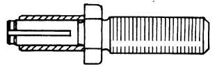
TACHOMETER DRIVE SHAFT
g.
Turn the crankshaft two complete revolutions
COUNTERCLOCKWISE (as seen from rear of
engine) and put timing pin (2) and bolt (3) in
again. If timing pin (2) and bolt (3) can not be
installed do Steps a through f again.
h.
Remove bolt (3) from the timing gear and install
in hole (5). Install the plug in timing hole (4).
Remove timing pin (2) and install bolt (1).
Install cover for the tachometer drive assembly
(6).
Checking Timing By Fuel Flow Method
Tools Needed:
1P540 Flow Checking Tool Group.
5P6524 Engine Timing Indicator Group.
9S215 Dial Indicator.
9S8883 Contact point .50 In. (12.7 mm) long.
8S2296 Rod 5.25 In. (133.4 mm) long.
5P7266 Adapter.
3P1565 Collet.
7M1999 Tube Assembly
2-50