TM 5-3825-226-24
FUEL INJECTION NOZZLES
4.
Install new O-ring seals on adapter (3) and fuel
injection nozzle (4).
5.
Install the fuel injection nozzle in the head.
Push and turn to install the nozzle into its
correct position. Never put lubricant on the
nozzle or bore in the cylinder head.
6.
Install the adapter in the head. Connect the
nozzle and fuel injection line to the adapter.
Tighten the nuts to a torque of 30 ± 5 lb.ft. (40
± 7 N m).
7.
Install the spacer and clamp that hold the nozzle
to the cylinder head.
end by:
a) install rocker shafts
DISASSEMBLE FUEL INJECTION NOZZLES
Tools Needed
A
B
C
D
8S2242
Nozzle Test Group
1
8S2250
Nozzle Holding Tool
1
5P958
Valve Retractor
1
5P4813
Socket
1
start by:
a) remove fuel injection nozzles
NOTE: Do not disassemble any nozzle until a test has
shown it is needed. Check each nozzle with tool (A) for
leakage, the pressure at which the nozzle opens, and
the shape and amount of fuel (spray pattern) that comes
out of the nozzle. Do not clean or make an adjustment
to any nozzle that has a large (excessive) amount of
return leakage. Excessive return leakage can be an
indication of nozzle failures that can not be corrected
with an adjustment or cleaning and can cause engine
damage.
See
TESTING
FUEL
INJECTION
NOZZLES
in
TESTING AND ADJUSTING.
CAUTION: Keep the work area and all tools extra
clean. Be careful not to cause damage to the parts
while the nozzles are disassembled and assembled.
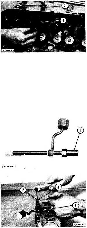
1.
Remove cap (1) from the fuel injection nozzle.
2.
Put the nozzle in tool (B). Put tool (B) and the
nozzle in a vise. Do not put any part of a nozzle
directly in a vise. Loosen locknut (2) while the
lift adjustment screw is held. Turn the lift
adjustment screw (3) counterclockwise one turn.
Hold the lift adjustment screw (3) with a 5/64"
hex wrench and remove the locknut (2).
CAUTION: If the lift adjustment screw is not turned
counterclockwise one turn, the valve can be bent or the
seat for the valve can be damaged when the pressure
adjustment screw is turned.
3-83