TM 5-3825-226-24
ENGINE
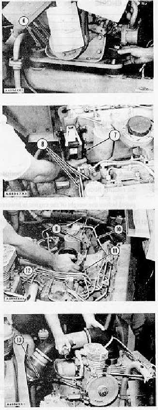
7.
Install the sleeves, upper halves of the mount
assemblies and tighten bolts (6).
8.
Remove the hoist from the engine.
9.
Connect fuel lines (8) to the junction block.
Connect drain hose (7) to the water separator.
10.
Connect wire (12) to the fuel shut-off solenoid.
11.
Pull the governor control cable through bracket
(10) and install the lockwasher, two locknuts (9),
the two grommets, the locknut and rod end (11)
on the cable.
12.
Connect rod end (11) to the governor control
lever.
13.
Connect the air indicator hose (13) to the air
cleaner housing.
14.
Put the air inlet tube assembly in position and
tighten the clamps for the hoses.
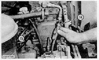
15.
Connect
hose
assembly
(15)
to
the
air
compressor governor and hose assembly (14) to
the air compressor.
3-136