TM 5-3825-226-24
DISC BRAKE ASSEMBLY
1. Head assembly. 2. Anchor pin. 3. Friction pad.
4. Metal backing. 5. Piston. 6. Disc.
Head Assembly
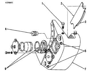
HEAD ASSEMBLY (CALIPER)
1. Anchor retaining bolt. 2. Metal backing. 3.
Friction pad. 4. Anchor pin. 5. Bleed valves. 6.
Piston and seal. 7. Head assembly.
Oil flow to the brakes is through lines and drilled
passages to all pistons within each head assembly.
When an application of the brakes is made, the
hydraulic pressure is made the same (balances) the
pistons and the force on each side of the disc is the
same. The pistons do not have return springs.
To make a pad replacement the caliper need not be
removed. For replacement of pads, remove the anchor
pin and slide the pad out.
CAUTION: Do not make a brake application with pads
removed. The pistons must not be permitted to extend
out of their bores as the pads are removed. Open the
bleed valves on the caliper to release any pressure on
the piston. If the pistons extend and let the seals come
out, caliper removal will be needed to install the pistons.
Two bleed valves on each caliper are used to let air
out of the hydraulic brake system. Let air out of the
brakes (bleed) whenever a line is disconnected in the
hydraulic brake circuit.
BRAKE ADJUSTMENT
Caliper disc hydraulic brakes need no adjustment.
There is no return mechanism to force the pads away
from the discs. The pads are in slight contact all the
time with the discs to keep them clean.
AIR IN THE HYDRAULIC BRAKE SYSTEM
Air in the hydraulic brake system cannot be detected
by brake pedal "feel." However, a stroke indicator (1) on
each master cylinder (2) will provide a means of
detecting a "soft" pedal condition which will cause
increased master cylinder piston movement. If the
movement of the stroke indicator is excessive (see
BRAKE SYSTEM TEST), check for hydraulic leaks or
air in the system.
NOTE: If the leak results from a damaged cup or seal,
the hydraulic brake system may be contaminated. Drain
the brake fluid and flush the system with denatured
alcohol. If the system is free of leaks, check for air.
Bleed each hydraulic brake system (see AIR REMOVAL
FROM BRAKES).
BRAKE SYSTEM TEST
Check of Operation
The stroke indicator (1) will give an indication when
brake repair is needed. With the brake pedal pushed
down, make note of the stroke of the rod (1) on each
master cylinder. Brake repair is needed when the stroke
indicator moves more than 1.00 in. (25.4 mm) from the
air chamber of the master cylinder.
5-17