TM 5-3825-226-24
LINES, PLUGS AND FITTINGS
HYDRAULIC LINE INSTALLATION
1.
For a metal tube to hose installation, install the
tube and tighten all bolts finger tight.
2.
Tighten the bolts at the rigid end.
3.
Install the hose and tighten all bolts finger tight.
4.
Put the hose in a position so that it does not
make contact with the machine or another hose.
5.
Tighten the bolts on both connections.
6.
Start the engine.
7.
Move the implement control levers to all
positions.
8.
Look at the hose during movement of the
implement. Make sure hose is not in contact
with the machine or other hoses.
9.
Shut off the engine.
10.
If necessary, put the' hose in a new position
where it will not make contact when the
implement is moved.
ASSEMBLY
OF
FITTINGS
WITH
STRAIGHT
THREADS AND O-RING SEALS
This type of fitting is used in many applications. The
tube end of the fitting will be different in design so that it
can be used in many different applications. However,
the installation procedure of the fitting is the same. If
the tube end of the fitting body is the same as in the
illustration (either an elbow or a straight body) it will be
necessary to assemble the sleeve on the tube before
connecting the tube to the end.
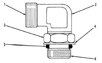
ELBOW BODY ASSEMBLY
1. End of fitting body (connects to tube). 2. Fitting
body. 3. Locknut. 4. Backup washer. 5. 0-ring seal.
6. End of fitting that goes into other part.
1.
Put locknut (3), backup washer (4) and O-ring
seal (5) as far back on fitting body (2) as
possible. Hold these components in this
position. Turn the fitting into the part it is used
on, until backup washer (4) just makes contact
with the face of the part it is used on.
2.
To put the fitting assembly in its correct position
turn the fitting body (2) out (counterclockwise) a
maximum of 359°. Tighten locknut (3) finger
tight.
NOTE
If the fitting is a connector (straight
fitting) the hex on the body takes the
place of the locknut. To install this
type fitting tighten the hex against
the face of the part it goes into.
TORQUES FOR FLARED AND O-RING FITTINGS
The torques shown in the chart that follows are to be
used on the nut part of 37° Flared, 45° Flared and
Inverted Flared fittings (when used with steel tubing), O-
ring plugs, O-ring fittings and swivel nuts when used in
applications to 3000 psi (20700 kPa).
A29919X2
1-61