TM 5-3825-229-14&P
4-12. CONTROL PANEL SWITCHES AND RELAYS
THIS TASK COVERS:
a.
Preliminary Testing Information
e.
Removal
b.
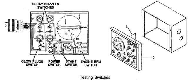
Testing Spray Nozzle Switches
f.
Installation
c.
Testing Power Switch and Glow Plug Switch
g.
Engine Relay Panel
d.
Testing Start Switch and Engine RPM Switch
INITIAL SETUP:
Tools Required:
Equipment/Materials Required:
Nomenclature:
Tags (Item 14, Appendix E)
General Mechanics
Equipment Conditions:
Tool Kit
Ref
Conditions
Multimeter 12-volt DC
power supply.
4-22 Battery cables disconnected
WARNING
Electric shock hazard exists. Disconnect battery cables (para. 4-22).
a. Preliminary Testing Information.
(1)
Unscrew two screws (1) on right side of panel (2). Open panel (2).
(2)
Tag and remove wires from switch(es) to be tested.
(3)
Prepare multimeter for ohms measurement per instructions supplied with multimeter.
4-21