Morse Controls
Use with Morse Connection Kits
and
Instruction Sheet
Type 33C “Red-Jaket” Cables
Model MT-2 Control
Introduction
These instructions, when used with the appropriate Throttle
Connection Kit and Clutch Connection Kit instructions, provide all the
necessary information for installing, adjusting and operating a Single or
Twin Morse Model MT-2 single lever control system.
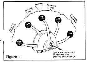
The Model MT-2 provides complete single lever control of both light
clutch and throttle operation in precise sequence for safe, one hand
engine control, as shown below (figure 1).
Full neutral throttle is provided for starting and warm-up by pulling out
the hand lever hub when the control is in neutral position. This locks
the control in neutral allowing full throttle range when lever is moved
forward. When the lever is returned to neutral, the hub automatically
snaps inward for single lever operation.
Equipment Required
The following components are required to make a remote control
installation for one engine:
1.
Model “MT-2” control head
2.
Clutch Connection Kit
3.
Throttle Connection Kit
4.
Two Morse 33C "Red Jaket" push pull cables
5.
Optional-Neutral Safety Switch Kit P/N A067925.
This kit is to provide start-in-gear protection to meet USCG
requirements 33CFR Part 183, Subpart L.
6.
Shift Travel Adapter Kit (P/N A304900) for longer shift travel in
Mercury I/O's since 1983.
Locate Control Head
When determining the position of the control head, consider the
following:
(a)
Allow clearance for full forward and ample reverse
movement of the control hand lever. (Figure 2).
(b)
The bottom of the control head housing should not interfere
with the steering gear or other components inside the
wheelbox.
(c)
The area below the control head housing should allow an
unobstructed path for running the control cables to the
engine. (See Figure 2).
After location of the control head is determined, use the template
provided and cut and drill the mounting holes required.
NOTE
Do not mount Control Head at this time.
2. Connect Clutch Cable to Control Head
1.
Open control head by removing screw (1) and (20).
2.
Remove screw (30) and lockwashers (9) and rotate retainer
plate and link (27) to uncover the clutch lever.
3.
Place jam nut (35) into pocket of terminal (26) then screw
terminal onto cable rod until 1/8” of rod is through terminal.
Hold terminal securely to prevent it from turning and tighten
cable nut against terminal.
4.
Lubricate terminal and place in proper hole in clutch lever as
shown in Figure 3.
5.
Mount Neutral Safety Switch at this time if required. Follow
instructions with switch kit. Replace retainer plate screws
and lockwashers.
MORSE
CONTROLS
21 Clinton Street
INCOM INTERNATIONAL INC
Hudson, Ohio 44238
INCOM
(213) 353-6461