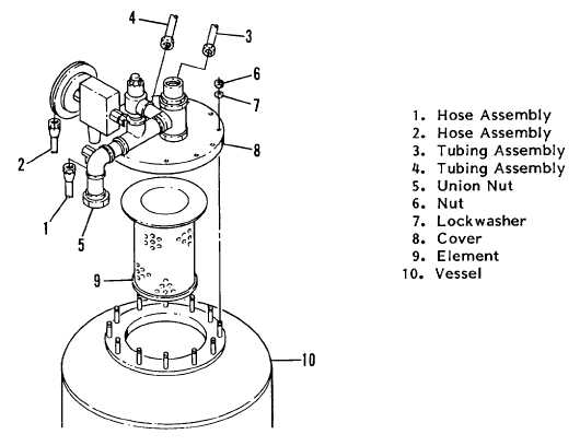
Figure 4-21F. Air/Oil Separator
4-7.5 Force Feed Lubricator.
4-7.5.1 Removing Lubricator Assembly (Figure 4-21G).
a.
Disconnect the copper tube assemblies; do not separate the tube assembly items (1, 2, 3, 4, 5) unless repair to
the lines is necessary. Disassemble the fittings and valves (items 6 through 12) as required for repair or
replacement.
b.
From the top of the lubricator, remove the elbows (13 and 14), tees (15), nipples (8 and 16), elbow (17), and
bushing (10). Remove the relief valve (18) and nipple (19) from the lubricator port plate (24). Finally, remove
the bolts (21) and lockwashers (22) to remove the lubricator motor guard (23).
4-7.5.2 Removing/Disassembling Lubricator Pump (Figure 4-21H).
a.
Remove the pump assembly (1) by first removing two capscrews (2) and washers (3). Lift the pump assembly
(1) and gasket (4) from the reservoir.
b.
Remove the strainer (5) and suction tube (6). Remove the retaining ring (7) and pull the pin (8) from the rocker
arm (9) and roller (10). Pull out the groove pin (11) to remove the rocker arm post (12). Remove the retaining
ring (13) to remove the spring retainer (14) and spring (15).
c.
Unscrew the plunger assembly (16) and the screw (17) from the pump body. Remove four capscrews (18) to
separate the housing assembly (19) from the pump body assembly. With the housing and body separated,
remove the packing (20, 21, and 22) and ball (23) from the pump body assembly (24). Repeat these procedures
for the other pump.
4-95


