Installation
Below Filter Fuel Storage
Application
1. Remove vacuum side filters in
fuel line between fuel tank and fuel
pump. Cast-in head or non-
removable
housing
should
be
adapted with the Racor Spin-On
By-Pass
(Part
NO.
11548).
Otherwise, service leave in place.
All secondary or pressure side
filters located between the pump
and engine should be serviced and
left in place.
2. Mount Racor Filter/Separator
vertically on the vacuum side of
the fuel pump or transfer
pump, whichever comes first, in a
convenient location for servicing
and
monitoring
contaminants.
Maintain vertical clearance above
filter
housing
for
removal
of
element
or
elements.
)See
500MA, 900MA, or 1000 MA Parts
Diagram.)
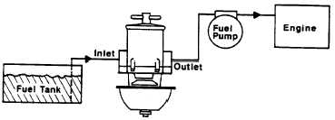
3. Position unit between the
horizontal planes of the bottom of
the fuel tank or day tank and pump
inlet for minimum restriction to the
pump. (See Figure 1).
4. Install fuel line from tank to inlet
side of the Racor unit using plated
steel fittings and maximum fuel line
size available in order to reduce
restriction. Any fuel by-pass or
return lines returning to suction
section of filter which are removed
must be routed into inlet
side of the Racor unit using plated
steel fittings. These fittings are
available
from
your
dealer
or
Racor Industries. Lubricate the O-
ring
of
each
fitting
before
installation. (Use clean diesel fuel
or a light oil.)
5. Install fuel line from the outlet of
the Racor unit to the inlet of the
transfer or fuel pump, again using
plated steel fittings.
6. Remove lid and prime the
system by pouring clean fuel into
filter cylinder until full. Replace lid
and hand-tighten the T-handle.
Carefully clean any accumulation
of diesel fuel from the metal
deflector bowl.
7. Start engine and test system.
See Troubleshooting Section.)
Figure 1
Installation
Above
Filter
Fuel
Storage
Application
1. Follow Steps 1 and 2 for Below
Filter Storage Application.
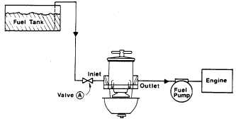
2. Position unit between fuel tank
and fuel pump inlet for minimum
restriction to the
pump. (See Figure 2.)
3. Follow Steps 4 and 5 for Below
Filter Fuel Storage Application.
4. On a 500Ma, 900MA, 1000MA,
73/1000A or 77/1000MA unit, a
valve must be installed on the inlet
side of the filter system. This valve
is
necessary
when
changing
elements. (See Figure 2 and
Accessories Section.)
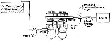
5. On a 75/900MA, 75/1000MA, or
79/1000MA unit, a pipe tee with a
compound
vacuum/pressure
gauge must be installed on the
outlet side of the filter system.
(See Figure 3 and Accessories
Section.)
6. Follow Steps 6 and 7 for Below
Filter Fuel Storage Application.
Figure 2
Figure 3
3
Maintain a minimum of 5-1/8” vertical
spacing between mounting clamps on
1000MA and 1000MAM.


