TM 10-5430-240-13&P 0004 00
0004 00-1/2 blank
OPERATOR, UNIT AND DIRECT SUPPORT MAINTENANCE MANUAL
(INCLUDING REPAIR PARTS AND SPECIAL TOOLS LIST)
TANK, FABRIC, COLLAPSIBLE, WATER, 3,000 AND 5,000 GALLONS, SEMI-TRAILER MOUNTED,
DESCRIPTION AND USE OF OPERATOR CONTROLS AND INDICATORS
GENERAL
This section lists major components, controls, and indicators, and describes the functions within the
collapsible fabric water tank assemblies.
DESCRIPTION AND USE OF MAJOR COMPONENTS
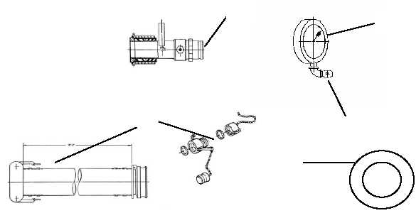
Typical illustrations are below. Descriptions and use of major components, including controls and
indicators, are listed in Table 1.
Table 1. Major Components, Controls and Indicators.
Key
Control or Indicator
Function
1
2
3
4
5
Filler/Discharge Valve
Pressure Gage
Pressure Gage Valve
Hose Assembly
Pressure Relief Valve
The filler/discharge valve is a 4-inch gate valve, which,
together with the hose assembly, provides the connection
necessary to both fill and empty the tank.
A 0 - 15 PSI pressure gage is supplied to monitor the
pressure of the filled tank. Operating pressure is 4 - 6 PSI.
The pressure gage is controlled by a .25 NPT valve. The
valve needs to be closed when the pressure gage is
removed.
The hose assembly consists of two, 10-foot long by 4-inch
diameter water hoses with quick disconnect fittings, dust
caps and plugs.
Located on the top of the tank, the pressure relief valve is
manually operated to relieve trapped air. It is opened and
closed with finger pressure.
END OF WORK PACKAGE
5
4
3
2
1


