TM5-3820-256-10
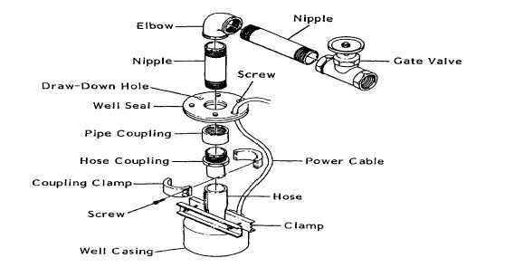
Figure 2-52. Sealing the Well.
(4)
Assemble the nipples to the elbow and insert one end through the well seal plate. Connect the nipple
to the hose with the pipe coupling. Install a gate valve on the other nipple.
(5)
Attach the auxiliary drum line to the elbow and lift the assembly enough to release the weight from the
clamp atop the well casing. Remove the clamp from the hose.
(6)
Lower the assembly into the well, guiding the well seal into the casing. Tighten the screws on the well
seal to compress and expand the seal's rubber center. Finally, remove the auxiliary drum line.
2-39.
Pump Starter Panel. (Figure 2-53)
a.
Attach starter panel to panel stands, using screws, lockwashers and nuts that are stored on panel standfoot.
b.
Stabilize the panel by placing sandbags on the stand feet or by driving stakes into the ground at holes in
stand feet.
c.
Turn the door locking screws one-half turn to disengage door locks. Open panel door.
d.
Cut outer insulation back on pump cable about twelve inches. Strip insulation on each lead to expose
approximately 3/4 inch of wire.
2-118


