SERVICE MANUAL
CYLINDER HEAD & VALVES
Section 3
2.
Turn the engine forward to approximately BDC
(Bottom Dead Center).
3.
Place a 0.10 mm (.004 in.) feeler gauge between
the valve lever and valve stem of the No. 1
intake valve and slowly rotate the engine forward
until the feeler gauge becomes tight. This is now
the point at which the No. 1 intake valve starts
to open before top dead center. The following
degree readings should be read on either
vibration damper or flywheel depending on the
application.
Engines
Readings
D-312 Below Eng. S/N 2505
30 ± 3
D-312 Eng. S/N 2505 and
23 ±
3
Above
D-360 and DT-360
30 ± 3
All 400 Series Engines
24° ± 3
NOTE: One (1) tooth "out of time" on gear train
equals approximately 11 degrees movement of
vibration damper.
NOTE: If the timing on the No. 1 valve is within
specifications, the other valves barring extreme
camshaft lobe wear or poor adjustment will also be
in time.
4.
Readjust the No. 1 intake valve to its proper
lash as described in this section.
5.
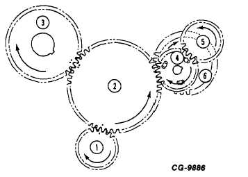
If timing is found to be incorrect, removal of the
engine's front cover is required to inspect punch
mark and gear tooth position. Figure 39 depicts
a properly timed assembly and number of teeth
between marks.
.
Crankshaft Gear
2.
Idler Gear
3.
Camshaft Gear
UTDS*
4.
Injection Pump Drive Gear
Model 100
5.
Tachometer Drive Gear
Fuel Injection
(if equipped)
Robert Bosch
6.
Injection Pump
Fuel Injection
Drive Gear
Model MW
Figure 39. - Properly Timed Gear
Train Assembly
22.5
TEETH BETWEEN PUNCH
MARK 1 AND PUNCH MARK 2.
CG-9885
*United Technologies Diesel Systems (formerly AMBAC)
CGES-185-3
PRINTED IN UNITED STATES OF AMERICA
Page 32