TM 5-3825-225-14&P
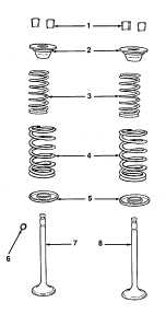
Figure 5-6. Valve Assemblies
(4) Grind valves and valve seats as necessary. Use grinding compound or grinding tools. Valves should
always be refitted to their original seats (see Chapter 1 for engine specifications).
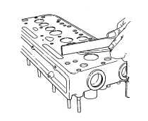
(5) Ensure that valve head depth is correct relative to the cylinder head face (see Figure 5-7). Place a
straight edge across the face of the cylinder head. Use a feeler gage to measure the valve head depth.
If the depth exceeds the maximum limit, install a valve seat insert (see paragraphs 1-42 and 1-43).
Figure 5-7. Gaging Valve Head Depth.
e. Disassembly of Rocker Shaft Assembly (See Appendix E Figure 57).
(1) Remove retaining rings (3) from each end of the rocker shaft (5).
(2) Remove rocker levers (15), springs (12), and support brackets (11) from rocker shaft (5).
(3) Remove connector (22) from rocker shaft (5).
f. Rocker Shaft Assembly Inspection (see Appendix E Figure 57).
Check rocker bearing sleeves (16) and rocker shaft (5) for wear. The rocker levers (15) should fit the shaft easily
without excessive play.
g. Assembly of Rocker Shaft Assembly (see Appendix F, Figure 57).
NOTE
Use the oil feed tube to locate the connector on the rocker shaft.
(1) Slide connector (22) over rocker shaft (5).
NOTE
When refitting new bearing sleeves, ensure that the oil feed holes line up before
pressing the bearing sleeves on the shaft.
(2) Lightly oil the components as the rocker shaft (5) is assembled to prevent the rocker levers (15) from
binding.
TA506333
5-11