TM 5-3825-226-24
TRANSMISSION CONTROL LINKAGE,
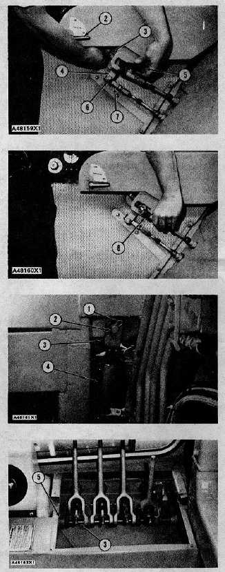
HYDRAULIC VALVE CONTROL LEVERS
2. Install the plate and handle (2) to the rod. Install the
pin in the handle. Install the rod assembly, spring
and spacer in the console. Install the three bolts to
the plate.
3. Put cable (7) through lever (4) and install nut (6).
Put lever (4) in position over the rod end and install
pin (5) through the lever and the rod end. Install the
nut on the back of pin (5).
4. Turn the shift lever in lever (4) and tighten locknut
(3).
5. Install transmission cable (8) to the pin.
REMOVE HYDRAULIC VALVE CONTROL LEVERS
Tools Needed
A
1P510
Driver Group
1
1. Remove clip (1) and pin (2) from jack (4). Pull the
jack free of the cab so shaft (3) can be removed.
2. To remove the knobs, the cover assembly and the
links from inside the cab, see REMOVE CAB, Steps
8 and 9 for details.
3. Loosen setscrew (5) on shaft (3).
3-333