TM 5-3825-226-24
Constant bleed valve (4) lets approximately 9 gallons of
fuel per hour go back to fuel tank (7). This fuel goes
back to fuel tank (7) through return line for constant
bleed valve (3). This flow of fuel removes air from
housing (14) and also helps to cool the fuel injection
pump. Check valve (D) makes a restriction in this flow
of fuel until the pressure in housing (14) is 8 ± 3 psi (55
± 20 kPa).
OPERATION OF FUEL INJECTION PUMPS
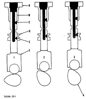
The main components of a fuel injection pump in the
sleeve metering fuel system are barrel (A), plunger (B),
and sleeve (D). Plunger (B) moves up and down inside
the barrel (A) and sleeve (D). Barrel (A) is stationary
while sleeve (D) is moved up and down on plunger (B)
to make a change in the amount of fuel for injection.
When the engine is running, fuel under pressure from
the fuel transfer pump goes in the center of plunger (B)
through fuel inlet (C) during the down stroke of plunger
(B). Fuel can not go through fuel outlet (E) at this time
because it is stopped by sleeve (D), (see position 1).
Fuel injection starts (see position 2) when plunger (B) is
lifted up in barrel (A) enough to close fuel inlet (C).
There is an increase in fuel pressure above plunger (B),
when the plunger is lifted by camshaft (4). The fuel
above plunger (B) is injected in to the engine cylinder.
FUEL INJECTION SEQUENCE
1, 2, 3. Injection stroke (positions) of a fuel injection
pump. 4. Injection pump camshaft. A. Barrel. B.
Plunger. C. Fuel inlet. D. Sleeve. E. Fuel outlet. F.
Lifter.
Injection will stop (see position 3) when fuel outlet (E) is
lifted above the top edge of sleeve (D) by camshaft (4).
This movement lets the fuel that is above, and in,
plunger (B) go through fuel outlet (E) and return to the
fuel injection pump housing.
When the sleeve (D) is raised on plunger (B), fuel outlet
(E) is covered for a longer time, causing more fuel to be
injected in the engine cylinders. If sleeve (D) is low on
plunger (B), fuel outlet (E) is covered for a shorter time,
causing less fuel to be injected.
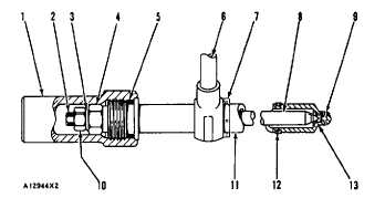
OPERATION OF FUEL INJECTION NOZZLE
The fuel inlet (6) and nozzle tip ( 13) are parts of the
nozzle body (II 1). Valve (8) is held in position by spring
force. Force of the spring is controlled by pressure
adjustment screw (3). Locknut (4) holds pressure
adjustment screw (3) in position. The lift of valve (8) is
controlled by lift adjustment screw (2). Locknut (10)
holds lift adjustment screw (2) in position. Compression
seal (7) goes on nozzle body (11).
The compression seal goes against inlet fitting (6) and
prevents the leakage of compression from the cylinder.
Carbon dam (12), at the lower end of nozzle body (11),
prevents the deposit of carbon in the bore in the cylinder
head.
FUEL INJECTION NOZZLE
1. Cap. 2. Lift adjustment screw. 3. Pressure
adjustment screw. 4. Locknut for pressure adjustment
screw. 5. O-ring seal. 6. Fuel inlet. 7. Compression
seal. 8. Valve. 9. Orifices (four). 10. Locknut for lift
adjustment screw. 11. Nozzle body. 12. Carbon dam.
13. Nozzle tip.
Fuel, under high pressure from the fuel injection pump
goes through the hole in fuel inlet (6). The fuel then
goes around valve (8), fills the inside of nozzle body
(11) and pushes against the valve guide. When the
force made by the pressure of the fuel is more than the
force of the spring, valve (8) will lift. When valve (8)
lifts, fuel under high pressure will go through the four
.0128 in. (0.325 mm) orifices (9) into the cylinder.
When the fuel is sent
2-10