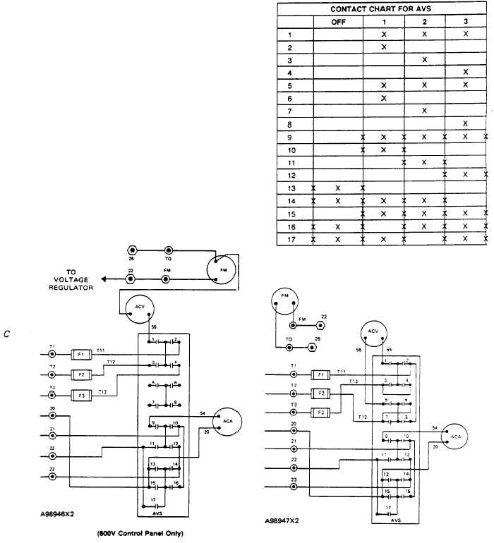
CONTROL PANEL (TYPE 3)
SYSTEMS OPERATION
ACA Alternating Current Ammeter
AC ammeter (ACA) gives an indication, in amperes,
of the current from each phase of the generator to the
load. Ammeter/voltmeter selector switch (AVS) is used
to connect the ammeter to the current transformer on
phase T1, T2 or T3; see Contact Chart. Ammeters
normally have an input range from 0 to 5 amperes.
Current transformer (CT1, CT2 or CT3) causes a
reduction of the actual line current, in its respective
phase lead, to a level within the input range of the
ammeter. The ammeter is calibrated (has marks) to give
an indication of the actual current flow in one phase load
of the generator.
NOTE: Several methods have been
used
to
connect
control
panel
instruments.
The
recommended
method is shown in the diagrams.
NOTE: X gives an indication of a
closed contact. .Y on the line gives
an indication of "make before break".
AMMETER/VOLTMETER SELECTOR SWITCH (AVS) WIRING DIAGRAMS
ACA
Alternating current ammeter
¤ Terminal point on TS2 in
ACV
Alternating current voltmeter
control panel
F1,2,3
Fuses
¤ Terminal Point on TS3 part
FM
Frequency meter
of voltage regulator
195


