SERVICE MANUAL
It is important that this valve be installed when any
auxiliary attachments are installed on a vehicle to avoid
complete loss of air in the event of an air leak in any of
the air operated attachments.
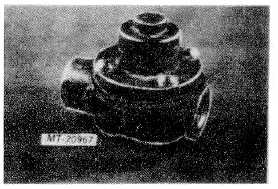
Fig. 4 Pressure Protection Valve
OPERATION
As long as the air supply pressure is below 448-517
kPa (65-75 psi) the spring will hold the diaphragm on its
seat restricting the air flow through the valve.
When the air supply pressure overcomes the spring
force, the diaphragm will move off the seat and allow air
to flow through the valve and to the auxiliary equipment
used on the vehicle.
If air pressure should fall approximately 138 kPa (20
psi) below the opening pressure, the spring force will
overcome the air pressure and force the diaphragm on
it’s seat closing off the air supply, protecting the air
system from a complete loss of air through usage of the
auxiliary equipment.
MAINTENANCE
Once each year or 160,000 km (100,000 miles)
remove the pressure protection valve, disassemble it and
clean all parts.
Replace the diaphragm if it is worn or deteriorated.
SERVICE CHECKS
Be sure the vent hole is not obstructed.
Bleed off main air supply.
Disconnect the air outlet side of valve, apply an air
pressure gauge known to be accurate with a shut-off
valve. Start engine and allow air pressure to build up.
Observe gauge on instrument panel and at valve outlet.
You should not have air pressure at test gauge until
main air reservoir pressure reaches 448-517 kPa (65-75
psi). Then the pressure protection valve opens and both
test gauge and gauge on vehicle should record
approximately the same.
Stop engine and open the shut-off valve at test
gauge. Air should exhaust until air pressure on vehicle
reaches a pressure at approximately 138 kPa (20 psi)
below opening pressure then stop. If the valve performs
as described the valve is functioning properly.
Bleed off main air reservoir pressure and remove
shut-off valve and test gauge. Reconnect line to the
auxiliary equipment.
REMOVE
Be sure to bleed off air reservoir pressure.
Disconnect air line routed to auxiliary fixture.
Remove pressure protection valve from connector.
REINSTALL
Install the pressure protection valve on same fitting valve
as was removed. Connect air line routed to auxiliary
fixture.
Build up air supply and check connections for air leaks.
DISASSEMBLY (Refer to Fig. 5)
1. Remove the four screws retaining upper and lower
body sections together. Care must be taken while
removing screws as the spring force will separate the
upper and lower bodies. MT-20968
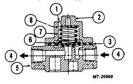
Fig. 5 Cross Section of Pressure Protection Valve
1
Vent Hole
5
Lower Body
2
Upper Body
6
Spring Cap
3
Diaphragm
7
Spring
4
Air Flow
8
Shim
CTS-4079-CHAPTER III
PRINTED IN UNITED STATES OF AMERICA
Page 5