TM 5-3825-226-24
FUEL INJECTION NOZZLES
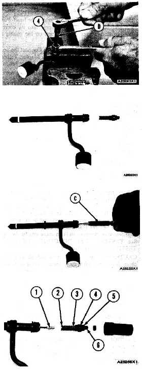
3.
Loosen the locknut (4) that holds the pressure
adjustment screw. Use tool (D) to hold the
pressure adjustment screw.
4.
While the nozzle is held in one hand, tilt the
nozzle and remove the pressure adjusting screw
and locknut, spring, seat and valve.
5.
If the valve does not slide out of the nozzle,
install tool (C) and remove valve as follows:
a)
Push valve into nozzle with tool (C) until
valve is against bottom of nozzle.
b)
Push down on body of tool (C) to engage
collet on valve with tool (C).
c)
Turn nut counterclockwise and remove
valve from the nozzle body. Put the parts
in solvent to loosen carbon and deposits
of
foreign
material.
The
body
is
assembled with an epoxy material and
must not be in contact with the solvent for
more than one to two hours.
ASSEMBLE FUEL INJECTION NOZZLES
Tools Needed
A
B
C
8S2250
Nozzle Holding Tool
1
8S2242
Nozzle Test Group
1
9S5031
Socket
1
NOTE: Make sure all of the parts have been thoroughly
cleaned before the nozzles are assembled. Flush the
body to remove any debris or lapping compound.
1.
Put clean fuel on all of the parts.
2.
Put valve (1) in position in the body as shown.
3.
Install lift adjustment screw (6) into pressure
screw (5). Turn the lift adjustment screw two or
three turns. Install the locknut (4) on the
pressure adjustment screw (5).
4.
Put spring (3), and seat (2) in position on the
adjustment screw (5).
5.
Put seat (2) in contact with the valve and push
the valve into position in the body. Tighten the
pressure screw by hand.
3-84