TM 10-4320-30313
1.15 LOCATION AND DESCRIPTION OF MAJOR COMPONENTS - CONTINUED .
Table 1-3. Description of Major Components for TWDS 10-Mile Hoseline Segment.
Item
No.
Item Name
Description and Purpose
1
6
INCH
X
500
FOOT
COLLAPSIBLE
HOSE
ASSEMBLY
Lightweight, collapsible, rubber hose used to transport water
up to 10 miles and to interconnect TWDS components.
2
FLAKING BOX
Each new Flaking Box holds two 500 foot hose assemblies.
Older models hold one 500 foot hose assembly. Allows hose
assembly to be flaked from back of truck. Adapted for forklift
and lifting sling.
3
SWIVEL JOINT
Placed between every 1,000 feet of hoseline to relieve
twisting and kinking of hoseline.
4
PRESSURE
REDUCING
VALVE ASSEMBLY
Provides protection for hoseline and other TWDS components
from excess pressure. Installed in hoseline where water
pressure is expected to exceed 225 pounds per square inch
(psi) and reduces pressure to 75 psi
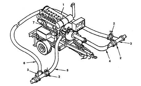
Figure 1-4. Location of Major Components for TWDS Boost Pumping Station.
Table 1-4. Description of Major Components for TWDS Boost Pumping Station.
Item
No.
Item Name
Description and Purpose
1
BOOST
PUMPING
STATION
600 GPM pumping assembly. Pumps water from lead
pumping station, or boost pumping station, and delivers it
down line. One of three pumping assemblies may be
supplied with the TWDS. Refer to applicable technical
manual for detailed information concerning the pumping
assemblies.
1-6


