AIR BRAKES - GENERAL INFORMATION
1.
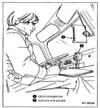
Mount a decelerometer (Figure 31) to the inside
windshield - as follows:
a.
Moisten the vacuum cups and press the
decelerometer assembly to the windshield
so it can be read by the observer.
b.
Loosen the bracket lower clamp nut and
adjust the decelerometer so that its sides
are-parallel to the direction of travel, then
tighten the clamp nut.
c.
Loosen the side adjusting clamp nut and
adjust the vertical position so that the fluid
registers zero when the truck is on level
ground, then tighten the clamp nut.
Figure 31 - Test Instrumentation (In-Cab)
2.
Install the single or duplex air test gauge (Figure
31) and connections as follows:
a.
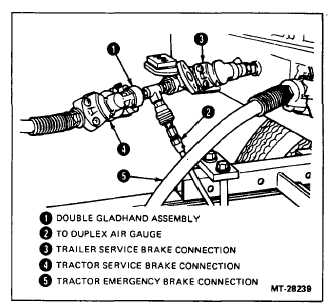
Install the double gladhand assembly in the
tractor to trailer service line (Figure 32).
b.
Mount the single or duplex test gauge in the
cab so it can be seen by both the driver and
the observer.
c.
Connect an air hose between the double
gladhand assembly and the gauge.
Figure 32Double Gladhand Assembly
Installation
d.
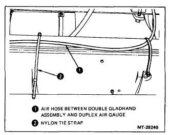
Secure the air hose to the vehicle so that it
will not snag when the vehicle is turned (Figure 33).
Figure 33 - Gauge Test Hose Routing
3.
Record the following Preliminary Data (vehicle
information) on the Data Sheet (CTS-1033Y)
before initiating the test:
a.
Typical Weight (estimated) for normal
maximum highway operation.
b.
Test Weight (actual axle weight or best
estimate). The vehicle should be loaded to
the extent that wheel lockup will not occur
with a 276 kPa (40 psi) brake application at
a test speed of 64 kmh (40 mph).
CTS-4154Y - Page 32


