AIR COMPRESSOR - MIDLAND BRAKE MODELS EL-1300, EL-1600
5.
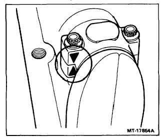
Turn compressor assembly over and position
connecting rod on crankshaft journal making
sure that the inserts are in place. Install caps
and inserts matching arrows on bearing cap and
rod as shown in Figures 11 and 12.
Tighten connecting rod bolts according to listing
In TORQUE CHART in this Section. Use a 12
point 5/16 in. socket on connecting rod bolts.
Figure 11 - Piston and Connecting Rod Assembly
Figure 12 - Connection
6.
Install the second connecting rod assembly in
the same manner.
CYLINDER HEAD
NOTE - Refer to Figure 5 during the following
procedures:
1.
Turn cylinder head upside down and insert new
washers (Item 12), exhaust valve springs (Item
9), exhaust valves (Item 10), and exhaust valve
seats (Item 11). Tighten exhaust valve seats to
torque valve specified in TORQUE CHART In
this Section.
2.
With head still positioned upside down, Insert
new washers (Item 12), inlet valve seats (Item
16), inlet valves (Item 13), inlet valve springs
(Item 15) and inlet cages (Item 14). Inlet valves
and springs must be centered to insure the valve
is not tightened between inlet valve seat and
cage. Tighten valve cage to specified torque
valve using valve cage tool SE-2613 as shown in
Figure 6. Refer to TORQUE CHART in this
Section.
UNLOADER
1.
Install new O-ring seals between flanges on
unloader pins. (Refer to Figure 4.)
2.
Form a 14mm (9/16 in.) ball of lubricant around
O-ring seal. Use a silicone lubricant which is
intended for dynamic lubrication between oil
resistant rubber seals and metal parts, meeting
MIL-L-4343A
requirements.
Dow-Corning
Corporation #33 medium weight grease is
suggested. (For optional lubricant refer to
BRAKES-AIR,
COMPONENTS,
General
Lubrication Specifications, Item 3.
3.
Position unloader assemblies and springs in
bores of cylinder head.
4.
Place unloader gasket on unloader cover.
Assemble these two items as a unit compressing
the unloader springs and hold until the unloader
cover bolts and lockwashers or hardened plain
washers are installed.
5.
Tighten unloader cover bolts to about 1.1 N-m
(10 lb-in) torque.
IMPORTANT - Unloader
cover
bolts
should
be
tightened
to
torque
valve
after
cylinder
head
bolts
have
been
tightened to second step torque
valve.
CYLINDER HEAD TO CYLINDER BLOCK
Position new cylinder head gasket on cylinder block.
With gasket aligned, position cylinder head on block.
Insert the longest head Volt through the unloader cover
center hole; the other five head bolts through the
remaining holes. Tighten head bolts in the sequence
noted in Figure 13. This is a two step process: first,
tighten to the first torque valve noted in TORQUE
CHART; second, retighten to second valve noted in
TORQUE CHART.
Tighten unloader cover bolts to torque valve listed in
TORQUE CHART in this Section.
CTS-4077Y
Page 11