AIR COMPRESSOR - MIDLAND BRAKE MODELS EL-1 300, EL-1 600
REMOVAL AND INSTALLATION
WARNING - WHEN ANY COMPONENT IS SER- VICED
OR REMOVED FROM THE AIR SYSTEM, BE SURE TO
SET THE PARKING BRAKE AND/OR BLOCK THE
VEHICLE TO PREVENT IT FROM MOV- ING WHILE
ANY SERVICE IS BEING PERFORMED. REMOVAL
1.
Drain air pressure from main reservoir.
2.
Drain engine cooling system and cylinder head
of compressor if compressor is water-cooled.
3.
Disconnect all air, water and oil lines leading to
and from the compressor.
4.
Remove compressor mounting bolts and drive
belts as required.
5.
Remove compressor from engine.
6.
Use suitable puller to remove pulley or gear from
compressor crankshaft after removing crankshaft nut.
7.
Inspect pulley or gear and associated parts for
wear or damage. If any parts are found worn or
damaged, they must be replaced.
INSTALLATION
Installation of compressor is performed by reversing the
removal procedures. Items to be observed when
reinstalling compressor are:
Clean oil supply line so that oil will flow freely through the
line.
Be sure oil return line or passages through brackets are
clean and unrestricted so that oil can return to engine.
Always use a new mounting gasket and be sure oil holes
in gasket and compressor are properly aligned with oil
supply line.
Inspect drive pulley (gear) for water or damage. It should
fit securely on the crankshaft, contacting the shaft only,
not riding the key. Tighten drive pulley nut to
recommended torque, refer to SPECIFICATIONS in this
Section.
Insure that the air cleaner is clean and properly installed.
If air intake is connected to the engine air cleaner,
connections should be tight with no leakage.
Clean or replace any dirty, corroded, or damaged air or
water lines before connecting them to the compressor.
Use a new discharge fitting gasket.
Align compressor drive and adjust to proper belt tension.
Tighten mounting bolts to recommended torque, refer to
SPECIFICATIONS in this Section.
After compressor is installed, operate it and check for air,
oil or water leaks at connections. Be sure to check for
noisy operation.
DISASSEMBLY
The air compressor crankcase, cylinder block and
cylinder head are designed so that these basic
components may be assembled In various ways to meet
various Installation requirements. To guard against the
parts being assembled incorrectly, these parts should be
marked in some manner prior to disassembly.
AIR CLEANER
Some compressor installations do not have a separate
air cleaner. These models are equipped with a hose to
the engine air cleaner and only the hose disconnect will
be required.
To remove the air cleaner, remove the two bolts which
secure the air cleaner and manifold to the cylinder head.
Remove air cleaner and manifold as one unit from air
compressor.
UNLOADER
1.
Bleed off main air reservoir. (For on vehicle
maintenance only.)
2.
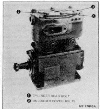
Remove two hex head unloader cover bolts and
cylinder head bolt located in center of unloader cover
(Figure 3).
Figure 3 - Unloader Cover Removal
3.
Remove unloader cover. Unloader seal and end
of pin will protrude from head.
4.
Remove unloader pins with seals and unloader
springs (Figure 4). Discard seals and cover
gasket.
CTS-4077Y - Page 6