SERVICE MANUAL
is between 524 kPa (76 psi) maximum and 441 kPa (64
psi) minimum. The contacts will be closed when warning
light or electrical buzzer operates.
Leakage Test
A small vent hole is provided in the cover of the
low pressure indicator to check the condition of the
diaphragm. Cover the vent hole with soap suds or use
Leak Detector (SE-2326); if a leak is indicated, it signifies
a ruptured diaphragm. Replace complete assembly.
REMOVE
1.
The ignition switch should be in the "off" position.
2.
Drain the air from the system.
3.
Disconnect the electrical connections at the Low
Pressure Indicator.
4.
Remove the Indicator from fitting.
REINSTALL
1.
Install indicator in fitting where old indicator was
removed.
2.
Connect electrical connections.
3.
Charge air system and perform Leakage Test.
Disassembly and reassembly of Low Pressure
Indicator is not recommended since it is only serviced as
a complete assembly.
STOP LIGHT SWITCH
DESCRIPTION
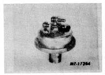
The stop light switch (Fig. 6) is an electro-
pneumatic switch which operates in conjunction with the
brake valve and stop lights by completing the electrical
circuit when a brake application of 35 kPa (5 psi) or more
is made.
Fig. 6 Stop Light Switch
Both the primary and secondary brake systems
are equipped with a stop light switch on a straight truck.
If a failure should occur in either the primary or
secondary systems,. The system which is functioning
properly will provide stop lights when the brakes are
applied.
MAINTENANCE
Every three months or every 40,000 km (25,000
miles, check all electrical connections.
Every year or 160,000 km (100,000 miles), the
stop light switches should be replaced.
SERVICE CHECKS
Operating Tests
1.
Both stop light switches must be checked
independently on a straight truck to be sure both
are functioning. Disconnect one switch.
2.
Apply brake valve and note that with first
downward movement of pedal or treadle that the
stop lights go on immediately.
3.
Release brake valve and note that stop lights go
off.
4.
If lights fail to go on use a test light at stop light
connections. Test both terminals to determine if
an electrical supply is available at switch; then
"bypass" the switch with test light or jumper wire.
Lights should go on. If not, a failure in the
electrical circuit is the problem. However, if
lights work, replace stop light switch.
5.
Repeat item 4 to check second light switch.
Leakage Test
With brakes applied there should be no air
leakage at stop light switch.
REMOVE
1.
Disconnect electrical connections. Be sure to
keep electrical connections from frame, etc.
Tape them.
2.
Remove switch from air fitting.
INSTALL
1.
Install stop light switch in air fitting.
2.
Install electrical connections.
3.
After stop light switch is reinstalled, perform
SERVICE CHECKS.
CTS-4079 - CHAPTER U -
PRINTED IN UNITED STATES OF AMERICA
Page 6