SERVICE MANUAL
DOUBLE CHECK VALVE
DESCRIPTION
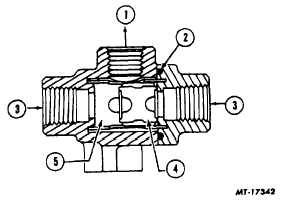
Double check valves or two-way check valves (Fig. 3)
are used in an air brake system where it is necessary to
automatically direct the flow of air pressure into a
common line from either of two other lines.
Fig. 3 Sectional View of Double Check Valve Shuttle
Type
1
Delivery
4
Shuttle Valve
2
"O" Ring
5
Shuttle Guide
3
Supply
OPERATION
As air pressure enters either end of the double .heck
valve (inlet port) the movable shuttle responds to the air
pressure and seals the line on opposite inlet port, but
permitting air pressure to ’low out the delivery (outlet)
port. The same action takes place if air pressure on one
side of shuttle is higher than that on the other side. It is
not necessary for the cavity of one side of shuttle to be
exhausted for valve to operate. Double check valves are
designed so it is impossible for shuttle to block outlet
port.
MAINTENANCE
Once each year or every 160,000 km (100,000 miles)
remove, disassemble, clean and inspect all parts. Install
new parts if signs of wear or deterioration are apparent.
SERVICE CHECKS
Due to the various applications of double check valves it
is best to bench test the valve using two separately
controlled air supplies and connected to inlet ports.
1.
Install an accurate test gauge in outlet port or in
a line from outlet port.
2.
Apply and release air to one inlet port and note
that gauge registers application and release.
3.
Repeat application and release of air to other
inlet port.
4.
Leakage check is performed at inlet ports by:
a.
Disconnecting line from one inlet port.
b.
Applying air to other inlet port. If soap solution is
used to check leakage, leakage should not
exceed 25.4 mm (1 in.) bubble in 5 seconds.
c.
Repeat step "b" by applying air to other inlet port
while checking opposite inlet port for leakage.
5.
If check valve does not meet requirements, it
should either be replaced or disassembled and
repaired using new parts.
DISASSEMBLY
1.
Remove end cap from valve.
2.
Remove O-ring.
3.
Remove shuttle (piston) and guide.
CLEANING AND INSPECTION
1.
Clean all metal parts in cleaning solvent.
2.
Inspect
all
parts
for
signs
of
wear
or
deterioration. Replace all parts not considered
serviceable.
3.
Replace all rubber parts.
REASSEMBLY
1.
Install shuttle guide and shuttle.
2.
Position new O-ring in end cap.
3.
Install end cap.
4.
Perform operating and leakage as described in
SERVICE CHECKS.
PRESSURE PROTECTION VALVE
DESCRIPTION
The pressure protection valve is designed to close off air
supply to any air operated device as long as the air
supply is below a specified rating.
The rating of the valve used in the FMVSS-121 air
system is 448-517 kPa (65-75 psi).
CTS-4079-CHAPTER III -
PRINTED IN UNITED STATES OF AMERICA
PAGE 4


