SERVICE MANUAL
DESCRIPTION
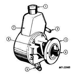
Fig. 1 Eaton Heavy Duty Roll Vane Pump
1
Reservoir Cap
2
Oil Return Inlet
3
Pump Mounting Flange
4
Pump Shaft
5
High Pressure Line Fitting
6
Pump Housing
7
Reservoir
The housing and internal pump parts are located
inside the reservoir so that the pump parts operate
submerged in oil. The reservoir is sealed against the
pump housing, leaving the housing face and shaft hub
exposed. A shaft seal and non-replaceable bushing are
pressed into the housing from the front. The drive shaft
is inserted through this seal and bushing. A large cavity
in the rear of the housing contains the rotating pump
parts. A smaller cavity contains the flow control valve
and spring.
The Eaton heavy duty roll vane pump can be gear or
belt driven. Both configurations are used on International
trucks.
MAINTENANCE
FLUID LEVEL
1.
Run engine until power steering fluid reaches
normal operating temperature, approximately
800C (1700F), then shut engine off. Remove
reservoir filler cap and check oil level on dipstick.
2.
If oil level is low, add power steering fluid to
proper level and replace filler cap. For
lubrication intervals, refer to Operator’s Manual.
For types of lubricant recommended refer to
Lubrication Section CTS- 4033.
3.
When checking fluid level after the steering
system has been serviced, air must be bled from
the system. Proceed as follows:
a.
With wheels turned all the way to the left
add power steering fluid to level indicated
on dipstick.
b.
Start engine, and running at idle, recheck
fluid level. Add fluid if necessary.
c.
Bleed system by turning wheels from side
to side without hitting stops. Maintain fluid
level so it is just visible in the reservoir.
Fluid with air in it will have a light tan or
milky appearance. This air must be
eliminated from fluid before normal steering
action can be obtained.
d.
Return wheels to center position and con-
tinue to run engine for two or three minutes,
then shut engine off.
e.
Road-test vehicle to make sure steering
functions normally and is free from noise.
f.
Recheck fluid level as described in Steps 1
and 2.
BELT TENSION
A belt that has been previously tensioned is
considered to be a used belt and should be tightened to
from 245 to 311 Newtons (55 to 70 lbs.). A belt that has
never been tensioned is considered to be a new belt and
should be tightened to 445 Newtons (100 lbs.).
Place Belt Tension Gage SE-2312, or equivalent,
midway between the pulleys on drive belt being checked.
BELT ADJUSTMENT
When adjusting a power steering pump belt, never
pry against the pump reservoir or pull against the filler
neck. To increase belt tension move the pump outward
by prying against the bracket pry lugs or against the
pump housing casting extension directly behind the
pump drive pulley.
1.
When power steering pump is driven by a single
belt:
a.
Loosen the pump attaching bolts and ad-
just the belt to correct tension by moving
the pump outward, away from the engine.
b.
Snug all pump mounting bolts and remove
pry bar.
CTS-4027 - Page 3


