III. AXLE ADJUSTMENT
A.
General
Adjustments
may
be
necessary
after
an
accident, in response to and to correct steering
problems, tire wear problems or as a part of the
reassembly process after a thorough inspection.
B.
Wheel Bearing Adjustment
1.
Raise the front of the vehicle with a jack and
secure vehicle with jackstands of suitable
capacity.
2.
Remove front wheels from vehicle.
3.
Remove the brake drum. (Disc style wheels
only.)
4.
With the end turned to full steering lock remove
the bolt and washer retaining the outer drive
yoke. (See fig. 14).
5.
Remove the nuts from the outer axle shaft drive
studs.
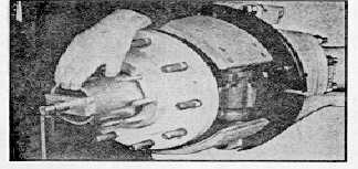
6.
The flange should be loose enough to remove by
hand. If not, use suitable bolts in the extractor
holes to remove the outer axle shaft. (See fig.
15)
Note: If oil is used for wheel bearing lubrication, care
should be exercised to protect brake linings, etc.
7.
Remove the wheel bearing lock nut (See fig. 4)
and lockwasher from spindle. Loosen wheel
bearing adjustment nut.
8.
Tighten wheel bearing adjusting nut while turning
the hub, back off 1/2 turn and then tighten to 50
ft. lbs. torque. (See fig. 4) Back off 1/4 turn.
Install the wheel bearing lockwasher with tang in
the spindle keyway and one side or the other
toward the bearing locknut in such a way as to fit
over the dowel.
Install the outer locknut and torque to
specification.
With
the
locknut
properly
tightened, end play should be between .001 and
.010 and the wheel hub should rotate freely.
Fig. 4
9.
Apply a bead of liquid sealant to outer axle shaft
flange. See Service Bulletin 738 407, Page 22.
10.
Insert the outer axle shaft into the spindle bore,
rotate and align the shaft splines with the outer
drive yoke splines, rotate the shaft and yoke to
align the shaft flange with the drive studs.
Back up drive yoke with suitable weight.
Tap axle shaft flange end to drive the shaft into
the drive yoke. Assemble the drive yoke
retaining washer with a new sealing washer, and
the bolt to the end of the axle shaft. See fig. 39,
page 19. Tighten to specified torque.
11.
Push axially on the outer drive yoke and check
for positive clearance under the axle shaft for
flange. The clearance should be at least
.015inch. (See fig. 40, page 19).
12.
Install axle shaft drive stud nuts. Tighten to
Specified torque.
13.
If wheel bearings are oil lubricated, refer to
Section II, A to refill.
C.
Kingpin Adjustment
1.
The front of the vehicle should be raised and
properly supported. Front wheels should be off
the axle.
2.
The lower kingpin jam nut should be loose or
loosened and the lower kingpin ball stud backed
down all the way.
3.
Raise the wheel hub, spindle yoke and kingpin
bracket assemblies with a hydraulic jack located
under the drum. On units with an upper kingpin
adjusting screw projecting through the upper
kingpin cap or steering arm, adjust the screw to
raise the aforementioned parts. Raise unit until
the upward movement is resisted by the bottom
of the upper kingpin bearing coming into contact
with the lower spherical surface of the upper
kingpin ball stud.
4.
Put a stack of feeler gauges between the lower
kingpin bracket and the suspension yoke. The
feeler gauges should fill the gap snugly.
5.
Turn the lower kingpin ball stud upward until the
stack of feeler gauges loosen (See fig. 5).
6.
Back off the lower kingpin ball stud one quarter
turn (900).
7.
Tighten the jam nut to the correct torque while
restraining the lower kingpin ball stud from
turning. On units with an upper kingpin adjusting
screw, back off the screw 1/4 turn. Restrain
screw while tightening locknut.
5-