SERVICE MANUAL
CONNECTING RODS, PISTONS, RINGS & SLEEVES
Section 5
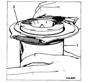
Figure 14. - Checking Piston Ring Gap
1. Piston ring
2. Feeler gauge
3.
Install new rings in the piston grooves with a
suitable ring installing tool as shown in Fig. 15.
a.
The No. 1 (compression ring) will have the
word “TOP” stamped on the ring.
b.
The No. 2 (intermediate ring) will be
marked “TOP”, “UP” or with a “PIP” on
the top side of the ring.
Check TOP and INTERMEDIATE Piston compression
ring groove widths for wear.
Figure 15. - Installing Piston Ring using Piston Ring
Expander Tool
1. Piston
2. Piston Ring Expander Tool
NOTE: A new piston groove wear measuring Tool
No. 3020 has been developed to accommodate the
complex configurations of International Harvester’s
technologically advanced pistons.
Tool Description: The Tool, No. 3020, consists of two
.0900 in. gauge pins and two 0.1150 in. gauge pins
mounted on springs (Fig. 16). The .0900 in. gauge pins
are used to measure piston groove wear on pistons with
half
keystone
INTERMEDIATE
compression
ring
grooves. The 0.1150 in. gauge pins are used to
measure piston groove wear on pistons with full keystone
TOP or IN-TERMEDIATE compression ring grooves.
The following checks are made to be sure that the
compression rings (keystone) fit are correct and not
carrying the piston load. If the measurement over gauge
pins is not within specifications, replace old pistons and
rings with new.
CGES-185-3
PRINTED IN UNITED STATES OF AMERICA
Page 16