SERVICE MANUAL
GENERAL
Section 1
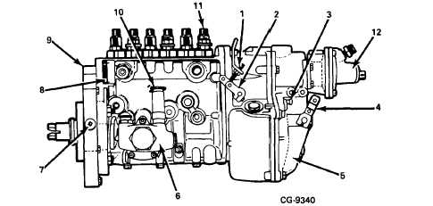
Figure 1. Robert Bosch Model MW Fuel Injection Pump
1.
Shut-off Stop Screw
5.
RQV Governor Housing
9.
Mounting Adapter
2.
Shut-off Lever
6.
Fuel Supply Pump
10.
Hand Priming Pump
3.
High Idle Stop
7.
Timing Pointer Plug
11.
Plunger
4.
Throttle Lever
8.
Serial Number Plate
12.
Aneroid
DESCRIPTION
The Robert Bosch Model PE(S)-6MW Injection Pump is
used on the International DT-466C diesel engine.
The injection pump is an in-line, plunger type, with an
individual plunger and barrel pumping element for each
engine cylinder. The injection sequence is 1,5, 3, 6, 2, 4.
The injection pump assembly incorporates mechanical,
flyweight type RQV variable speed governor.
The pump throttle lever and the high-speed stop screw
are located on the left side of the governor assembly.
The fuel shut off lever is also located on the left side of
the governor.
The injection pump is located on the left side of the
engine. High pressure lines connect the pump to the
nozzles. Operating and service instructions for the
nozzles are given in CGES-200-2 Service Manual.
IDENTIFICATION
Identification of injection pump and governor can be
made by referring to two nameplates, one on the rear of
the governor housing, and one on the front top left of the
injection pump (Figure 2). The nameplate on the rear of
the governor gives the IH part number of the complete
pump and governor assembly and the Robert Bosch
governor number, size and rating. The nameplate on the
left side, gives the Robert Bosch pump description
number.
OPERATING PRINCIPLES
The injection pump is the in-line type with an individual
plunger and barrel pumping element for each engine
cylinder. Each plunger stroke is constant, but its
effective pumping (metering) stroke is variable and is
controlled by the positioning of a common control rack
connected through linkage to the governor and the
vehicle’s throttle lever.
The individual plunger and barrel pumping elements
receive fuel at supply pump pressure from the injection
pump housing fuel gallery, and forces it under very high
pressure through the injection nozzles into the engine
combustion chamber.
The injection pump plungers are moved by tappet
assemblies which ride on the lobes of the injection pump
camshaft. The injection pump camshaft is timed to the
engine to inject fuel into each cylinder at the proper time.
CGES-375
Printed in United States of America
Page 1