SERVICE MANUAL
GENERAL
Section 1
Supply Pump With Hand Priming Pump
The piston-type supply pump (6, Figure 1) is activated by
the eccentric on the injection pump camshaft and serves
as a mount for the hand priming pump (10, Figure 1).
Since all fuel entering the injection pump must be filtered
to ensure long pump life, the hand priming pump should
be used when changing fuel filters. Always install the
fuel filters "dry" and use the hand pump to fill the filters
and bleed air from the fuel system.
Aneroid Assembly
Exhaust smoke levels during engine acceleration are
controlled by using an aneroid (12, Figure 1). The
aneroid limits fuel delivery during acceleration until the
turbocharger speed is sufficient to provide adequate air
for complete combustion. An external line connects the
intake manifold to the aneroid to allow manifold pressure
to activate the aneroid. A leak in the aneroid diaphragm
or intake manifold to aneroid line will cause the injection
pump to stay in the "cutback" position, and reduce
engine power.
Fuel Return Valve
A fuel return check valve is mounted to the injection
pump housing (1, Figure 6) and all fuel that is not
injected passes through the check valve and then
through a special orificed rubber hose. The function of
the fuel return check valve is to provide
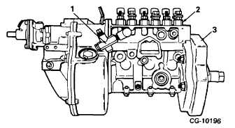
Figure 6. Right Side View of Injection Pump
1.
Fuel Return Valve
2.
Delivery Valve Holder
3.
Drive Gear
a positive seal to prevent fuel from draining out of the
pump housing when the engine is stopped. The fuel
return check valve opens at approximately 18 psi.
Therefore, total fuel flow through the injection pump
housing is controlled by the orifice in the rubber hose as
long as the supply pump pressure is above 18 psi. After
the fuel flows through the orifice, the fuel pressure drops
from the intermediate pressure ahead of the orifice to
low pressure (Figure 4).
GOVERNOR
The mechanical flyweight governor (5, Figure 1) which is
mounted on the injection pump, is the variable speed
type, identified by the manufacturer as ROV 350-1200
(or -1300). The 350-1200 (or -1300) designation refers
to the injection pump speed range in which the governor
functions. This corresponds to 700 to 2400 (or 2600)
engine RPM, since the pump camshaft rotates at 1/2
engine speed. Figure 7 illustrates a typical cut-away
view of the RQV governor
Figure 7. Cut-Away View of Governor Assembly
1.
Stop Shackle
7.
S-Plate
2.
Rack Link
8.
Guide Pin
3.
Control Rack
9.
Adjusting Pin
4.
Governor Springs
10.
Guide Lever
5.
Bell Crank
11.
Rocker Arm
6.
Sliding Block
12.
Aneroid
CGES-375
Printed in United States of America
Page 5