TM 5-3825-226-24
2.
Fasten .25 in. (6.4 mm) I.D. (inside dimension)
hoses to the bleed screws that lets the air out.
Put the loose end of the hoses into ajar that has
enough fluid in it so that the end of the hoses
are under the surface of the fluid.
3.
Push the brake pedal down and release it
several times until the indicator rods make a
shorter stroke.
4.
Keep the brake pedal down and look at the
indicator rod.
5.
Open the bleed screws that lets the air out and
look at the fluid that comes out of the hoses.
Close the bleed screws when the indicator rod is
extended 1.44 in. (36.6 mm).
6.
Do Steps 3, 4, and 5 until the fluid that goes out
of the hoses has no air bubbles.
7.
Fill the reservoir to .50 in. (12.7 mm) from the
top of the reservoir when necessary.
8.
If necessary do the above procedure for the
water distributor.
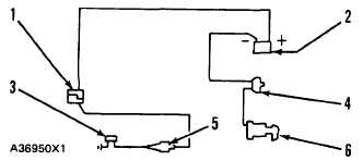
ELECTRIC WARNING SYSTEM
NOTE
Before any test is made of the
electric warning system, check all
electrical connections and grounds
to assure good contact.
Start the engine and allow the air system pressure
to build up to cutout pressure and shut off the engine.
Turn the disconnect switch ON.
Slowly let the air pressure out by pushing down on
the brake pedal. Note the air pressure shown on the
gauge at which the buzzer begins to sound. This should
be at approximately 60 psi (415 kPa).
ELECTRIC WARNING SYSTEM
1. Pin connector. 2. Ammeter. 3. Low air pressure
warning buzzer. 4. Circuit breaker. 5. Low air pressure
buzzer located under the dash. 6. Starter switch.
If the buzzer does not begin sounding in the correct
pressure range, check continuity of the normally closed
pressure switch. The switch should be closed. If the
switch is good, check the buzzer. If either is defective,
install a new component.
CONTROL VALVE FOR PARKING BRAKE
Start the engine and let the air pressure go up to
cutout pressure. Stop the engine and push the knob of
the control valve IN. Let the air pressure out of the
reservoir by pushing the foot pedal down again and
again. Read the pressure on the test gauge at which the
knob comes out and the emergency brake goes ON.
The knob must come out at 40 + 5 psi (280 + 35 kPa).
If the knob does not come out, and valve has a
defect, install a new valve.
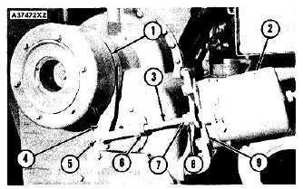
Make a full extension of pull rod (3) from brake
chamber (2). Use 75 psi (520 kPa) (minimum) air
pressure in chamber (2) if available. If no air pressure is
available, loosen locknut (7) and turn nut (8) clockwise
on pull rod (3) until nut makes contact with plate (9).
Turn nut (8) more so pull rod (3) moves to the left, out of
chamber (2). This action will cause compression of the
spring inside chamber (2) and release the parking brake.
Make the adjustment to rod end (5) so it will connect
to brake lever (4) when lever (4) is moved in the
direction of chamber (2). Move lever (4) enough so the
brake shoes start to make contact with the drum (1).
Make the connection and tighten locknut (6). Turn nut
(8) to a position of 1.25 in. (31.8 mm) from plate (9) and
tighten locknut (7).
ADJUSTMENT OF THE PARKING BRAKE
1. Brake drum. 2. Brake chamber. 3. Pull rod. 4. Brake
lever. 5. Rod end. 6. Locknut. 7. Locknut. 8. Nut. 9.
Plate.
2-142


