TM 5-3825-226-24
CONNECTING RODS
Leave the connecting rod in the checking fixture and
check for both bores parallel. Make a record of the
readings for both dial indicators. The total difference
between indicator readings is the bores parallel
dimension. The maximum allowable dimension is .006
in. for rods that are acceptable for reconditioning.
A check can also be made to check for connecting
rod twist. Push one end of the pin mandrel against the
locating surface behind it. Use a thickness gauge on the
opposite end to check the clearance between the
mandrel and the locating surface. Check both ends of
the mandrel in this way for clearance. The amount of
clearance is the twist in the rod. The maximum
allowable twist is .012 in. for rods, that are acceptable
for reconditioning.
BORING PISTON PIN BEARING
After new piston pin bearings are: installed in the
connecting rods, use the 5P3550 Connecting Rod
Boring Machine to bore the piston pin bearings to the
correct size.
Install the cap on the connecting rod (do not install
the bearings). Tighten the nuts as shown in the
SPECIFICATIONS.
Put-the 5P2010 Mandrel on the spindle. Install nut
and actuator, and tighten to hold mandrel in position.
Install 5P2013 Plunger Extension on the plunger. The
plunger must be in the up position within ± 3°. Loosen
the spindle carrier, and use the handle on top to adjust
the bearing bore center-to-center dimension. Move the
carrier until the vernier scale reads 7.6867 ± .0010 in.
This is the correct scale dimension to get a bearing bore
center-to-center dimension of 7.9000 ±
.0010 in.
Tighten the carrier in this position.
Put the connecting rod in position on the mandrel,
with the boss on the pin end of the rod towards the left.
Turn the actuator until the connecting rod is tight on the
mandrel.
Install 5P3552 Bushing in the front bracket. Push the
locating arbor through the front bushing. Put 5P3541
Locating Bushing, with the large dimension of the
diamond shape horizontal, on the locating arbor. Slide
the locating arbor through the connecting rod and into
the rear bushing. Slide the locating bushing into the rod.
Push the locating rods until they are against the
connecting rod, and tighten the rods firmly. Remove the
locating arbor end bushing.
Fasten the 5P2023 Tool Bit Setting Gauge to the
boring bar. Be sure the contact point of the indicator is
against the boring bar. Adjust the indicator so the
revolution counter and the hand are at zero. Move the
tool bit setting gauge so that the contact point is against
the cutting edge of the tool bit. Fasten the gauge in this
position. Loosen the screw that holds the tool bit. Make
an adjustment to the tool bit until the indicator reads
.1881 in. Tighten the screw that holds the tool bit and
recheck the setting.
Put the boring bar through the connecting rod and
into the rear bushing. Install the front bushing over the
boring bar and into the bracket. Install 5P4777 Torsion
Bracket on the rear of the boring machine. Put 5P4778
Feed Cylinder so the shaft goes through the rear
bushing and into the boring bar. Tighten the setscrew in
the boring bar to hold the feed cylinder shaft. Adjust
torsion bracket and feed cylinder so the boring bar
moves smoothly in rear bushing.
NOTE: Put the feed lever on the feed cylinder in the
OPEN position before moving the boring bar.
With the feed lever in the OPEN position, move the
boring bar until the tool bit is .125 in. (3.2 mm) from the
bearing in the connecting rod. Put the feed lever in the
CLOSED position and tighten the thumbscrew on the
cylinder against the torsion bracket shaft. Install
5P2055 Flexible Adapter in the front of the boring bar
and fasten an electric drill to the adapter. Put oil on the
boring bar at the front and rear bushings. Start the drill
and let the feed cylinder pull the boring bar through the
bearing. Use a slow feed rate and do not push on the
drill.
Check the bearing bore with a new piston pin. If the
fit is too tight, do the boring operation again with the
SAME tool bit setting.
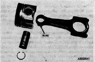
Install the connecting rod into the piston with the boss
on the rod on the same side as the crater in the piston.
CONNECTING ROD AND PISTON
When the connecting rod and piston assembly is
installed, use new connecting rod bolt nuts.
3-382


