TIMING CASE AND DRIVE - K.5
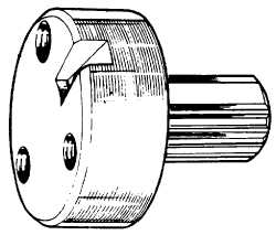
Fig. K.8.
Adaptor PD67B-1.
will ensure that all backlash is taken up at T.D.C.
Refit valve spring cap and collets.
2.
Fit adaptor PD67B-1 (see Fig. K.8) to the fuel
pump gear so that dowel of gear locates in slot
of adaptor and shaft of adaptor is towards rear
of engine. Secure adaptor to gear using gear
securing setscrews.
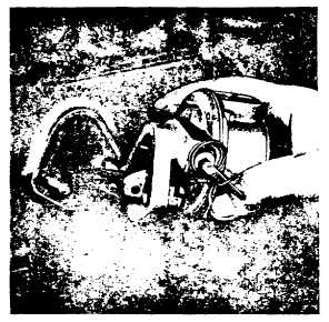
Fig. K.9.
Marking Scribed Line on Rear of New Timing Case.
3.
Release screw (5) of timing tool MS67B (see Fig
N.10) and remove splined shaft.
4.
Ensure slotted pointer (2) of timing tool is
positioned with slot to front of tool and
chamfered sides of slot outwards. At this stage,
slotted edge of pointer should be kept well back
from front of body. Ensure that flat of washer
fitted behind pointer securing screw (3) is
located over pointer.
5.
Release the bracket locking screw (4) and set
bracket so that the chamfered edge is in line
with the relevant engine checking angle (see
Page B.11).
6.
Pressing fuel pump gear and adaptor towards
rear, with the fuel pump gear timing mark
located correctly with the idler gear timing mark,
locate splined shaft of adaptor into timing tool
with master spline engaged and adaptor shaft in
timing tool with rear face of adaptor abutting
front face of timing tool.
7.
Move tool forward, complete with gear so that
register of tool locates in pump aperture of
timing case. If pointer is 180° out, then engine is
on wrong stroke and tool should be removed
and engine set on correct stroke.
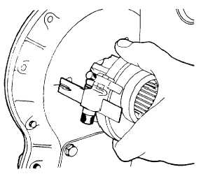
Fig. K.10.
Removing the Fuel Lift Pump.
8.
Slide slotted pointer forward to reach rear face
of timing case and lock in position.
9.
Take up backlash by turning tool against normal
direction of rotation (shown on pump nameplate)
and mark the scribed line on the rear of the
timing case to coincide with the centre of the slot
in the pointer (see Fig. K.9).
10.
Remove tool and adaptor from fuel pump gear
and fit fuel pump to engine as detailed on Page
N.6.
To Remove the Camshaft and Tappets
Camshaft end float is controlled by a thrust plate
located in a recess machined in the front face of the
cylinder block. The plate is dowelled to


