TM 10-4320-303-13
Figure 2-10. First Boost Pulping Station Location.
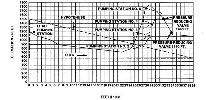
2.3.1.8 Determine Location of Second Boost Pumping Station. To determine second boost pumping
station location, place pump spacing triangle zero mark on the first boost pumping station mark on ground
profile graph. Mark point at which pump spacing triangle hypotenuse crosses ground profile. This identifies
second boost pumping station location. Locations of successive boost pumping stations are determined using
the same procedure.
2.3.1.9 Determine Location of Pressure-Reducing Valve Assembly. After locations of pumping stations
have been plotted, check ground profile for any sharp declines in elevation along hoseline route. An excessive
drop in elevation will significantly increase water pressure as water flows downhill.
CAUTION
To prevent damage to TWDS components do not allow water pressure to exceed
225 psig.
If pressure builds to 225 psig, hoseline can rupture and equipment failure will result. Therefore, when a sharp
elevation drop along hoseline route -is indicated by the ground profile graph, a pressure-reducing valve
assembly must be installed in the hoseline. To determine pressure-reducing valve assembly location, refer to
ground profile graph and proceed as follows:
2-34