VI. STEERABLE DRIVE END ASSEMBLY
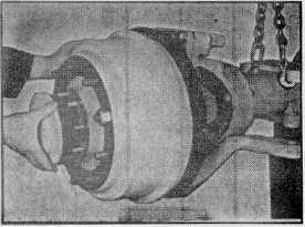
Fig. 38
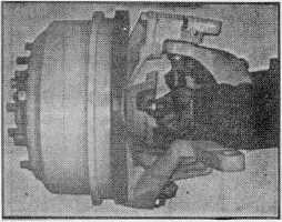
Fig. 39
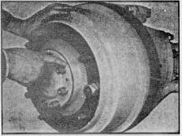
Fig. 40
J.
Universal Joint Assembly
Install the universal joint cross and bearing assembly
with two bolts in each of the bearing caps. (See figs. 27
and 20). Rotate the wheel hub to rotate the universal
joint while the end is turned against the steering stop and
check for positive clearance. (See fig. 9).
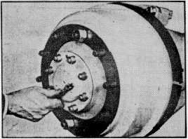
Fig. 41
K.
Brake Actuator Chamber Installation
If not already on the assembly, add the brake
actuator chamber. Assemble a collet nut on the actuator
chamber tube so that the tapered part of the nut will fit
into actuator. Screw the actuator chamber into the
actuator until the tube is tight against the wedge stop
washer. Tighten the collet nut securely (150 ft. lbs.
torque).
L.
Steering Arm Assembly
Install the steering arm and upper kingpin bearing
cap. Note that the short studs are used on the outboard
end when installing the steering arm and the long studs
on the inboard end. Use flexloc nuts on the studs. The
cap is held in place with bolts and lockwashers.
M. Tie Rod Assembly
Install the steering connecting tie rod. Tighten the
castle nuts to the specified torque and use new cotter
pins.
N.
Final Assembly
1.
Make adjustments as described in Section IIl.
2.
Lubricate and add lubricants as described in
Section II.
3.
Install wheels and tires. Torque wheel nuts to
specifications.
4.
Lower the vehicle to the ground and road test.
-19-