SERVICE MANUAL
TIMING, GEAR TRAIN & FRONT COVER
Section 7
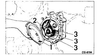
With Crankcase front cover on (Refer to Figures 14
and 14a
1.
Remove the pump access cover (1).
2.
Remove the three drive gear bolts (2) securing
the gear to the pump adapter and timing plate.
3.
Remove the gear (3) as shown.
Figure 14. - Removing Injection Pump Drive Gear
(UTDS* Model 100 Fuel Injection Pump) [with front cover
on] )
1.
Access cover
2.
Injection pump drive gear
3.
Drive gear bolts (3)
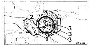
Figures 14a. - Removing Injection Pump Drive Gear
(Robert Bosch Model MW Fuel Injection Pump) [with
front cover on] )
1.
Access cover
2.
Injection pump drive gear
3.
Pump drive gear bolts and washers (3)
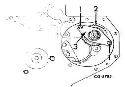
If necessary remove the Tachometer Drive Gear as
follows: (For engines equipped with UTDS* Model
100 fuel injection pump)
1.
Remove the two nuts (1, Fig. 15) and thrust
plate (3), as shown.
2.
Remove the spacers (from the mounting studs)
and remove the gear (2, Fig. 15) from the dowel
in the injection pump mounting adapter.
If necessary remove the Crankshaft Drive Gear and
Oil Pump Drive Spline as follows:
1.
Remove crankcase front plate and crankshaft.
(Refer to Section 6).
2.
With
the
crankshaft
removed
from
the
crankcase, support the front of the crankshaft.
Figure 15. - Removing Tachometer Drive Gear (UTDS*
Model 100 Fuel Injection Pumps)
1.
Nut
2.
Tachometer drive gear
3.
Thrust plate
*United Technologies Diesel Systems
(formerly AMBAC)
CGES-185-3
PRINTED IN UNITED STATES OF AMERICA
Page 8