SERVICE MANUAL
ROBERT BOSCH MODEL MW INJECTION PUMP
Section 11
11. Verify alignment of pump timing pointer to hub mark
through mounting adapter opening (Figure 23).
Rotate pump drive hub as required for proper
alignment. Torque pump drive gear bolts to 35 ft-lbs.
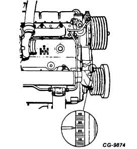
(47 N•m). Observe engine to injection pump timing
on pulley (Figure 24). Refer to Chart 1 on Page 19,
this section, for correct timing.
Figure 24. - Engine to Injection Pump Timing on Pulley
12. Install drive gear access cover.
13. Install lubricating oil line to injection pump.
14. Install fuel supply, fuel return and high pressure
injection pipes with all clamps and brackets. Clean
inside of each injection pipe with filtered air before
assembling to injection pump and nozzles.
INJECTION PUMP DELIVERY VALVE HOLDER
MUST BE HELD WITH A WRENCH TO PREVENT
MOVEMENT WHEN HIGH PRESSURE PIPING IS
BEING INSTALLED (refer to Figure’20).
15. As applicable, install electric shutoff assembly,
ground and power supply wire.
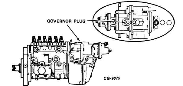
16. Add minimum of one pint of engine oil to governor
through the upper governor housing plug (Figure 25).
Because injection plug is splash lubricated, engine
oil must be added to a replacement pump.
17. Install throttle cable or linkage to outer control lever.
Adjust throttle cable or linkage so tang in outer
control lever is in "override position." At "override"
lever tang will be approximately half way from center
of control lever to end of slot.
Figure 25 - Governor Housing Plug
CGES-185-3
PRINTED IN UNITED STATES OF AMERICA
Page 19


