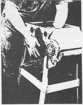
Fig. 26
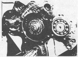
Fig. 27
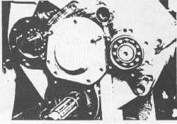
Fig. 28
7.
Fit direct drive gear (Item 40) onto shaft with
chamfered spline side toward the front of the case so
the chamfer will fit up onto the split retaining ring
(See Fig. 25 and Fig. 26).
8.
Install the spacer washer (Item 41) and the roller
bearing inner race (Item 42) on the shaft. The
shoulder on the race should be toward the gear; this
will allow the cover and the roller bearing outer race
and roller assembly to fit over the inner race (See
Fig. 27).
9.
Install the retaining washer (Item 43) and locknut
(Item 1) on the shaft (also shown in Fig. 27).
10. Tighten the nut on the speedometer gear end of the
shaft to specifications while restraining the nut on the
roller bearing end of the shaft.
11. The rear nut should be tightened to specifications
while the front output yoke is restrained from turning.
12. Install the alignment studs in preparation for
installation of the intermediate shaft rear cover.
13. Install cover gasket and cover pulling into place with
Permatexed bolts. Tighten the bolts to the specified
torque. Note: No end play adjustment is required.
14. Remove washers and bolt that were installed in step
F1. Position the speedometer cap gasket (Item 30)
over the front of the intermediate shaft with the oil
return hole in the gasket and the case aligned.
15. Put the speedometer cap (Item 29) in place with the
speedometer cable connection pointing in the same
direction as it was when it was removed from the
case. Attach with bolts that have been coated on
their threads with Permatex; tighten bolts to correct
torque.
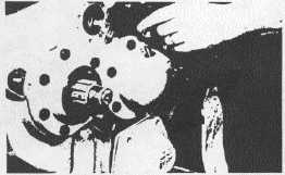
16. Install the speedometer driven gear (Item 27) and
speedometer driven gear sleeve (Item 26) in
speedometer cap (See Fig. 29).
17. Install vent (Item 28) in speedometer cap.
Fig. 29
-21-


