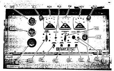
CONTROL PANEL (TYPE 4)
SYSTEMS OPERATION
COMPONENTS
NOTE: For specifications on components
located on the engine, make reference to the
ENGINE SERVICE MANUAL.
CONTROL PANEL (TYPE 4 - CHANGE LEVEL 9 THRU 11)
ACA
Alternating current
FM
Frequency meter
VLR
Voltage level rheostat
ammeter
PL1,2
Panel lamps
1.
Button (Direct current ammeter
ACS
Engine control switch
PLS
Panel lamp switch
DCA)
ACV
Alternating current
OCI
Overcrank indicator
2
Button (heat switch HS, if
voltmeter
OPG
Oil pressure gauge
so equipped)
AVS
Ammeter/voltage selector
OPI
Oil pressure indicator
3.
Panel (Prealarm module
switch
OSI
Overspeed indicator
PAM, if so equipped)
WTG
Water temperature gauge
WTI
Water temperature indicator
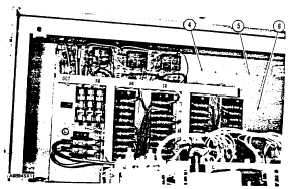
INSIDE CONTROL PANEL
(TYPE 4 - CHANGE LEVEL 9 THRU 11)
4. Location for CDT (cool down timer, if so equipped). 5.
Location for AUX (auxiliary relay, if so equipped). 6.
Location for CCM (cycle crank module, if so equipped).
216