CONTROL PANEL (TYPE 4)
SYSTEMS OPERATION
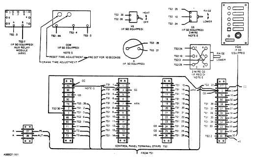
CONTROL PANEL COMPONENTS (PARTIAL) AND CONTROL PANEL
TERMINAL STRIP TS2
NOTE A: Wire and cable shown dotted to be
furnished by customer.
NOTE B: To be wired to engine starting contact
(N.O.) in auto transfer switch by customer.
NOTE C: Each wire on terminal strip is identified on
each end corresponding to terminal strip number.
NOTE D: Remove yellow wire and insulate from
terminal 7 at TS3 before connecting wire from TS2.
NOTE E: Use 3 wire diagram with sodine 3 wire
synchronizing motor. Use 2 wire diagram with 2
wire permanent magnet motor.
NOTE F: To be wired to auxiliary contact (N.O.) on
emergency side of transfer switch. Req'd only when
optional generator set Annunciator panel (remote) is
provided. (generating indication).
NOTE G: Red jumper wire from TS2-4A to TS2-4
must be removed when cycle cranking module is
used.
NOTE H: Do not operate alternator without a battery
connected in the system. Do not polarize alternator.
Do not operate alternator simultaneously with a DC
generator to charge a common battery.
NOTE I: Provide 24 volts for remote low oil pressure
(pre-alarm) (OPP) indication when pre-alarm module
is used.
NOTE J: Provides 24V for customer provided
remote shutdown and pre-alarm indicator when pre-
alarm module is used.
213