CONTROL PANEL ATTACHMENTS
SYSTEMS OPERATION
HEAT SWITCH
NOTE: Available on Type 2, Type 3 and Type 4 control
panels.
Heat switch (HS) is used on generator sets equipped
with glow plugs. When the heat switch is held closed,
magnetic switch (MSG) is energized. This closes
magnetic switch contacts and glow plugs (GP) heat the
precombustion chambers to aid cold weather starting.
When the heat switch is released, the magnetic switch is
de-energized and current flow to the glow plugs stops.
NOTICE
Do not energize the glow plugs when
the engine is warm.
AMMETER
NOTE: Available on all control panels.
Ammeter (A) is a DC ammeter used to show the rate of
charge or discharge in the alternator circuit. The
purpose of the optional alternator circuit is to charge
batteries (BATT).
GOVERNOR- SWITCH
NOTE: Available on all control panels.
When the engine governor is equipped with a
synchronizing motor, governor switch (GS) is used to
change engine rpm. Move the switch up to increase
rpm, down to decrease rpm.
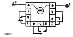
AUXILIARY RELAY MODULE
NOTE: Available on all control panels.
Auxiliary relay module (ARX) is in a parallel circuit with
arming relay (AR). The (ARX) coil is energized during
engine operation. The auxiliary relay module has both
normally open and normally closed contacts. They are
available for use as desired by the customer.
AUXILIARY RELAY-MODULE (ARX)
SYNCHRONIZING LIGHTS MODULE
NOTE: Available for Type 3 and 4 control panels. This
module is located in the same place as Prealarm module
(PAM).
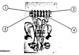
BACK OF SYNCHRONIZING LIGHTS MODULE
1. Terminal L3.
3. Terminal L1.
2. Terminal T1.
4. Terminal T3.
Terminal T1 (2) connects to a terminal of phase 1 on the
generator side of the circuit breaker.
Terminal T3 (4) connects to a terminal of phase 3 on the
generator side of the circuit breaker.
Terminal L3 ( I) connects to the terminal of phase 3 on
the load side of the circuit breaker.
Terminal L1 (3) connects to terminal of phase 1 on the
load side of the circuit breaker.
NOTE: IF the synchronizing lights rapidly go ON and
OFF, when the engine is running, do not close the circuit
breaker. Check for one of the conditions that follow.
Engine speed (frequency) not the same as the load.
Voltage level not the same as the load.
Wires from the synchronizing lights module not
correctly connected to the phase terminals on the circuit
breaker.
If each light goes ON and OFF, but not at the
same time, the phase rotation of the generator is
opposite to the phase rotation of the load.
NOTICE
Never close the circuit breaker with
either synchronizing light ON or with
switch OFF.
266