TM 10-4320-303-13
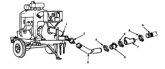
Figure 2-18. Boost Pumping Station and Suction Components Assembly.
a. Remove plastic cap from suction port (Figure 2-18, 1) on 600 gpm pumping assembly, reference
applicable technical manual for suction port location on 600 gpm pumping assemblies not shown. If
plastic cap has not been removed, remove it and retain cap for movement or storage.
CAUTION
After removing components from boxes, be sure to protect them from sand and
grit. Sand and grit in components may cause damage to components themselves
and 600 GPM pumping assembly.
b. Attach 6 inch x 10 foot hose assembly (3) to suction port (1) with grooved-end pipe quick disconnect
coupling clamp (2) (para 2.3.3.2).
c. Install 6 inch butterfly valve (5) on end of 6 inch x 10 foot hose assembly (3) with grooved-end pipe
quick disconnect coupling clamp (4) (para 2.3.3.2).
d. Install 6 inch lateral grooved pipe fitting (7) on end of 6 inch butterfly valve (5) with grooved-end pipe
quick disconnect coupling clamp (6) (para 2.3.3.2).
e. Install grooved-end pipe quick disconnect coupling clamp (8) on end of lateral grooved pipe fitting (7)
(para 2.3.3.2) and connect 500 foot hose assembly (9).
2-45