TM 10-4320-303-13
2.3.8 Assembly of 10-Mile Hoseline Segment . (Continued)
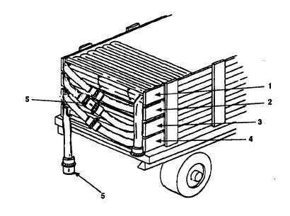
Figure 2-34. Grooved Pipe Coupling and Swivel Joint installation.
CAUTION
Install swivel joint after every 1,000 feet of hoseline, 2 hoseline segments.
Failure to install swivel joint every 1,000 feet may result in damage to
equipment.
NOTE
Newer flaking boxes contain 1,000 foot sections of hose.
c. Connect swivel joint (5) to leading end of hose in flaking box three (3) with 6 inch grooved pipe
coupling (para 2.3.2.2).
d. Connect trailing end of hose in flaking box two (2) to swivel joint (5) with grooved-end pipe quick
disconnect coupling (para 2.3.3.2).
e. Connect leading end of hose in flaking box two (2) to trailing end of hose in flaking box one (1) with 6
inch grooved pipe coupling (para 2.3.2.2)
CAUTION
Install swivel joint after every 1,000 feet of hoseline, 2 hoseline segments.
Failure to install swivel joint every 1,000 feet may result in damage to
equipment.
f. Connect swivel joint (5) to trailing end of hose in flaking box four (4) with 6 inch grooved pipe coupling
(para 2.3.2.2).
g. Connect leading end of hose assembly (Figure 2-35, 1) in flaking box one (Figure 2-34, 1) to pressure
relief valve (Figure 2-35, 2) on discharge hose (3) at lead pumping station (4). Attach leading end of
hose (1) with grooved- end pipe quick disconnect coupling clamp (5) (para 2.3.3.2).
2-68


