S-SERIES AIR CONDITIONING - HEATER SYSTEM
4.
Disconnect
wiring
harness
connector
from
blower switches.
5.
Remove blower switch mounting screws and
remove switch from control assembly.
Installation
1.
Position blower switch to control assembly, and
install switch mounting screws.
2.
Connect
wiring
harness
connector
to
blowerswitch.
3.
Position control assembly in instrument panel
and install trim plate and mounting screws.
Reinstall ash tray, if removed.
4.
Install knob onto blower switch lever.
5.
Tum key switch ON and check operation of
blower switch. Tum key switch OFF after
operation test.
HIGH-SPEED
AND
LOW
PRESSURE
SWITCH
RELAYS Removal
1.
Disconnect battery cable.
2.
Remove cover from right side of instrument
panel.
3.
If relays are accessible, proceed to step 4. If
relays cannot be reached, remove radio/ash tray
panel, as follows, to gain access to the relays.
a.
Remove radio/ash tray panel mounting
screws and pull panel outward.
b.
Disconnect radio power feed wire, speaker
leads and antenna lead from radio.
c.
If necessary, disconnect hourmeter, front
wheel
drive
warning
light,
engine
oil
temperature gauge and transmission oil
temperature gauge wiring.
d.
Disconnect ash tray light from ash tray
frame.
e.
Remove radio/ash tray panel.
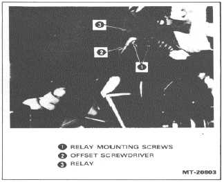
4.
Using offset screwdriver or screwdriver socket,
remove relay mounting screws and remove
relay(s) from air duct (Figure 30).
5.
Disconnect wiring harness connectors from
relay(s).
Installation
1.
Connect wiring harness connectors to relay(s).
2.
Position relay(s) on air duct and install mounting
screws. Use offset screwdriver or screwdriver
socket to tighten screws.
3.
Reinstall radio/ash tray panel and related parts
(if removed).
4.
Reconnect battery cables.
5.
Tum key switch ON and check operation of
relay(s). Turn key switch OFF after operation
check.
Figure 30. - Removing Relay
6.
Install instrument panel cover.
CTS-4066A
Page 19