TM 5-3825-229-14&P
4-12. CONTROL PANEL SWITCHES AND RELAYS (cont)
g. Engine Relay Panel (cont).
(2)
Testing (cont).
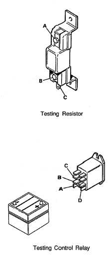
(a)
Testing Glow Plug Resistor (cont).
3.
Connect one lead of the
multimeter to terminal "A".
Connect the other lead to
terminal "B". The reading
should show continuity or very
little resistance.
4.
Connect one lead of the
multimeter to terminal "A" and
the other lead to terminal "C".
The reading should show
continuity or very little
resistance.
5.
If there is no continuity and
resistance is noted in either
test, replace resistor.
(b)
Testing Control Relay.
1.
Connect terminal "A" to
negative (or ground) of a 12-
volt DC power supply or
battery.
2.
Connect terminal "B" to
positive of a 12-volt DC power
supply or battery.
3.
Prepare multimeter to read DC
voltage per instructions
supplied with multimeter.
4.
Check voltage at terminal "C"
with multimeter. Voltage
should be zero. If voltage is
present, replace relay.
5.
Connect terminal "D" to positive of a 12-volt DC power supply or battery.
6.
Check voltage at terminal "C" with multimeter. Voltage should read 12 volts. If
voltage is not 12 volts, replace relay.
4-26