TM 5-3825-229-14&P
6-11. PISTONS AND CONNECTING RODS (cont)
c.
Cleaning and Inspection (cont).
(4)
Check piston ring groove side clearance. Clearance must be as shown below:
Ring
Groove Side Clearance (MAXIMUM)
Top Rings
0.0098 inch (0.25 mm)
Intermediate Rings
0.010 inch (0.25 mm)
Oil Control Rings
0.006 inch (0.15 mm)
(5)
Calculate piston to cylinder wall clearance.
(a)
Measurements of the pistons, cylinder bores, and clearances between pistons and cylinder bores should
be taken at 70°F (21C). Pistons must be fitted to their respective cylinder bores before the rings are
installed to provide a specific clearance.
(b)
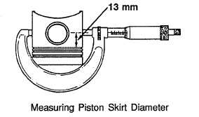
Measure outside diameter of piston skirt 0.05 in. (13 mm) below oil ring at a right angle to the piston pin
using an outside micrometer. Diameter must be as shown below.
(c)
Nominal diameter limit minimum must be 3.4971 in. (88.827 mm). Worn diameter limit minimum must
be 3.4946 in. (88.762 mm).
(d)
Cylinder bore honed diameter should be 3.5034 to 3.5044 in. (88.987 to 89.013 mm). Allowable wear
limit is 3.5064 in. (89.063 mm).
(e)
The difference between the two readings is the piston-to-cylinder clearance. If clearance exceeds wear
limit, cylinder bore should be resized to the smallest standard oversize diameter at which it will clean
up. Clearance should be 0.0057 to 0.0079 in. (0.145-0.201 mm). Maximum allowable wear limit
clearance is 0.0107 in. (0.273 mm).
(6)
Clean oil and crankcase deposits from connecting rod and cap. Be sure funnel oil hole is clean and open.
(7)
Check connecting rods for nicks, cracks and damaged bolt threads. Replace as necessary.
6-25


